Image pickup apparatus and control method therefor

a technology of image pickup and control method, which is applied in the field of switching control technology, can solve the problems of difficult operation of the operating member on the back face of the camera, unintended function execution,

Active Publication Date: 2019-09-26
CANON KK
View PDF7 Cites 1 Cited by
  • Summary
  • Abstract
  • Description
  • Claims
  • Application Information

AI Technical Summary

Benefits of technology

[0007]Aspects of the present invention have been made in view of the above-described issues and provide an image pickup apparatus that can appropriately set a time until a state is shifted to a power saving state in response to a use state or the like of a shooting apparatus such as self-shooting.
[0008]In addition, aspects of the present invention have been made in view of the above-described issues and provide an image pickup apparatus that can switch, for example, on and off of a display unit such as a touch panel at a satisfactory operability.
[0009]According to an aspect of the present invention, there is provided an image pickup apparatus including an accepting unit configured to accept an operation from a user, a display unit that selectively changes a display direction to one of an image pickup direction of an image pickup unit or an opposite direction, a power saving unit configured to execute a power saving function of reducing power consumption in response to a period in which the accepting unit has not accepted the operation from the user exceeding a threshold, and a control unit configured to perform control such that the threshold in a case where the display direction of the display unit is the image pickup direction is set to be longer than the threshold in a case where the display direction of the display unit is the opposite direction.

Problems solved by technology

On the other hand, in recent years, the number of cameras provided with a touch panel that can accept the touch operation on its back face has been increased, and in a case where the user walks while wearing the camera around the neck or the like, the body of the user may contact the touch panel, and an unintended function may be executed in some cases.
In this manner, when the power supply is turned on in response to the touch operation, if the body of the user or the like touches the touch panel, an unintended operation may be performed in some cases to cause an undesirable result.
Meanwhile, as described in Japanese Patent Laid-Open No. 2013-254007, when the shooting is performed while the display unit is inverted, the user is likely to be situated on an image pickup side (front face side) of the camera, and it is facilitated to perform the touch operation on the display unit, but it is difficult to operate an operating member on the back face of the camera.

Method used


Image

  • Image pickup apparatus and control method therefor
  • Image pickup apparatus and control method therefor
  • Image pickup apparatus and control method therefor

Examples


first exemplary embodiment

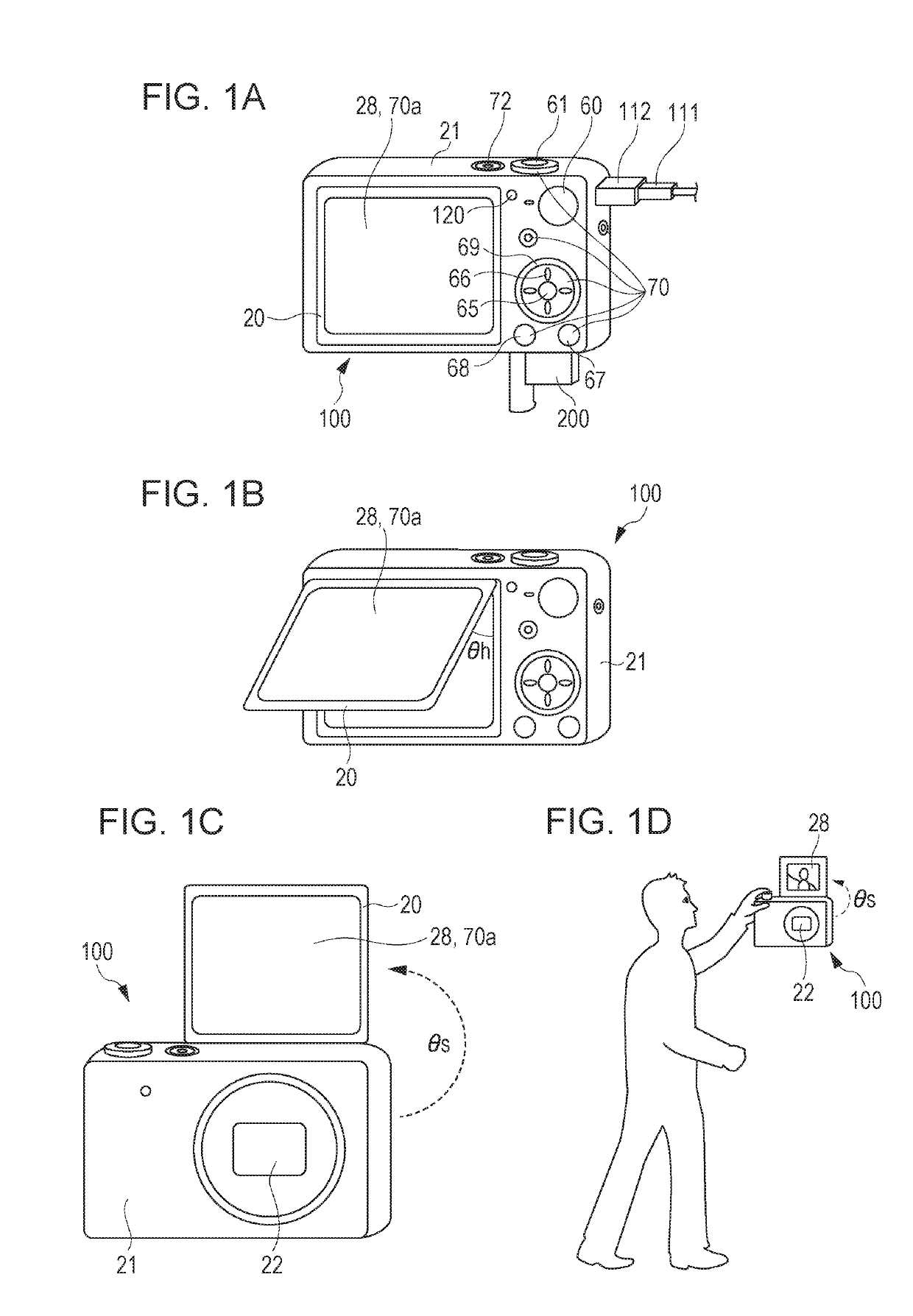
[0018]FIGS. 1A to 1D illustrate an external appearance of a digital camera 100 as an example of an image pickup control apparatus according to an exemplary embodiment of the present invention.

[0019]The digital camera 100 is constituted by a main body unit 21 and the monitor unit 20, and the monitor unit 20 is rotatable (its position can be changed) within a predetermined range with respect to the main body unit 21. Thus, a user can selectively change a display direction of a display unit 28. FIG. 1A illustrates a state in which the monitor unit 20 is stored in the main body unit 21, and a rotation angle θ=0 is set. FIG. 1B illustrates a case where the monitor unit 20 is rotated by the rotation angle θ=θh with respect to the main body unit 21, but the display unit 28 and an image pickup unit 22 face in opposite directions to each other so that the display unit 28 is not checked from the user situated on the side of the image pickup unit 22. FIG. 10 illustrates a case where the monito...


PUM


Abstract

An image pickup apparatus includes a display unit that changes a display direction to at least one of an image pickup direction of an image pickup unit or an opposite direction, a power saving unit that executes a power saving function of reducing power consumption in response to a period in which an operation from a user has not been accepted exceeding a threshold, and a control unit that performs control such that the threshold at a time when the display direction is the image pickup direction is set to be longer than the threshold at a time when the display direction is the opposite direction.

Description

CROSS-REFERENCE TO RELATED APPLICATION[0001]This application is a Divisional of U.S. application Ser. No. 15 / 167709, filed May 27, 2016, which claims priority from of Japanese Patent Application No. 2015-114265, filed Jun. 4, 2015, and Japanese Patent Application No. 2015-114266, filed Jun. 4, 2015, which are hereby incorporated by reference herein in their entireties.BACKGROUNDField[0002]Aspects of the present invention generally relate to a switching control technology for a power saving state and a non-power saving state.Description of the Related Art[0003]Up to now, to reduce power consumption of an apparatus, a technology has been proposed for performing an auto power-off operation when a state in which no operation has been performed on the apparatus continues for a predetermined time or longer to shift the state into a power saving state. To avoid the auto power-off operation while the non-operation state continues for the predetermined time or longer when the shooting is per...

Claims


Application Information

Patent Timeline
Patent Type & Authority Applications(United States)
IPC IPC(8): H04N5/232H04N5/225G06F1/3234G06F1/3231
CPCH04N5/23293G06F1/3265H04N5/23219G06F1/3231H04N5/232411Y02D10/153H04N5/23212H04N5/2252H04N5/23241H04N5/23216Y02D10/173Y02D50/20H04N23/531H04N23/675H04N23/60H04N23/651H04N23/632Y02D10/00Y02D30/50H04N23/51H04N23/67H04N23/62H04N23/611H04N23/00H04N23/683H04N23/66
Inventor NABESHIMA, RUI
Owner CANON KK
Why Eureka
Try Eureka