LCD type 3D printer

a 3d printer and lcd technology, applied in the field of lcd type 3d printers, can solve the problems of difficult and time-consuming to precisely manufacture a product, short printing time, and high manufacturing cost, and achieve the effects of reducing the size of the 3d printer, preventing overexposure of the lcd panel, and extending the service li

Inactive Publication Date: 2019-10-03
RAY
View PDF5 Cites 4 Cited by
  • Summary
  • Abstract
  • Description
  • Claims
  • Application Information

AI Technical Summary

Benefits of technology

[0045]In addition, since the mask image is not applied to the LCD panel, it is possible to prevent overexposure of the LCD panel to ultraviolet rays, thereby extending the service life thereof.
[0046]Moreover, the light irradiation angle can be narrowed by the meniscus lens or the convex lens. Thus, the light source can be disposed at a distance shorter than the focal distance of the Fresnel lens, thereby reducing the size of the 3D printer.

Problems solved by technology

The above-mentioned mock-up method is cost-effective but is disadvantageous in that it is difficult and time-consuming to precisely manufacture a product.
In addition, the cutting method using a machine tool can precisely manufacture a product but has a disadvantage in that it takes a lot of manufacturing cost and suffers from a restriction on the producible shape.
Among the aforementioned types, the DLP type is configured to laminate one surface at a time and, therefore, the printing time is short.
However, the DLP type has a disadvantage in that the resolution varies depending on the printing area.
Thus, the quality of the molded product 50 is deteriorated.
However, when ultraviolet rays are used as a light source, there is a possibility that the LCD panel 30 is damaged by strong ultraviolet rays.
Therefore, there is a problem that the LCD panel 30 is damaged and the service life thereof is shortened.

Method used


Image

  • LCD type 3D printer
  • LCD type 3D printer
  • LCD type 3D printer

Examples


first embodiment

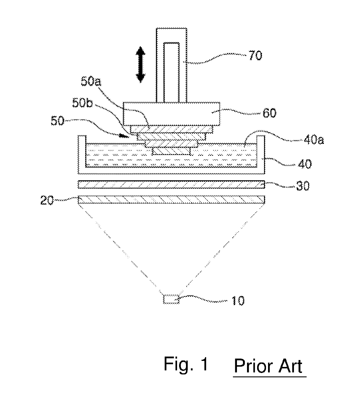
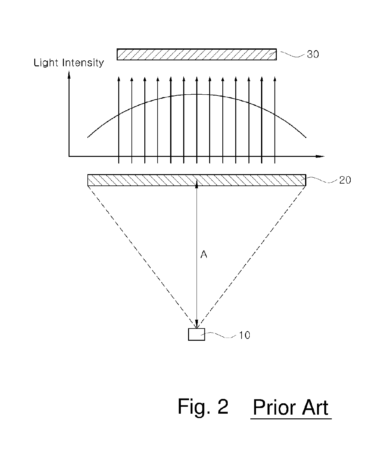
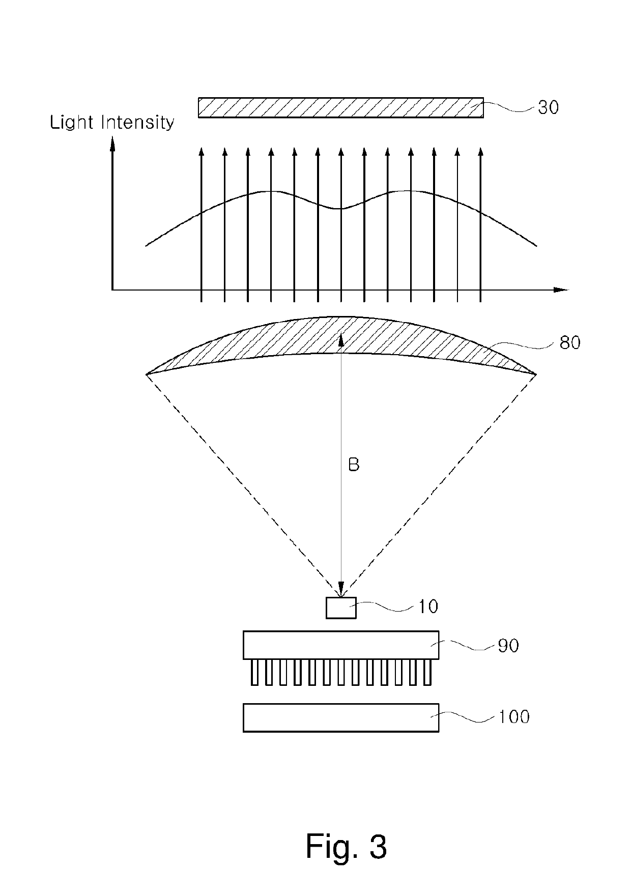
[0052]FIG. 3 shows a LCD type 3D printer according to a first embodiment of the present invention. As shown in FIG. 3, the LCD type 3D printer according to the first embodiment of the present invention includes a light source 10 provided at a lower portion of the 3D printer to irradiate light upward, a lens disposed at a predetermined distance from the upper portion of the light source 10, an LCD panel 30 provided above the lens, a storage container 40 provided above the LCD panel 30 to store a liquid molding material 40a, a build plate 60 provided above the storage container 40 to hold a molded product 50, and an elevating member 70 provided at the upper portion of the build plate 60 to move up and down.

[0053]An upwardly-convex meniscus lens 80 or a convex lens (not shown) capable of reducing a light irradiation angle is provided between the light source 10 and the LCD panel 30.

[0054]The meniscus lens 80 refers to a lens having two spherical curved surfaces, convex on one side and ...

second embodiment

[0086]FIG. 4 shows an LCD type 3D printer according to a second embodiment of the present invention.

[0087]As compared with the first embodiment, the LCD type 3D printer according to the second embodiment of the present invention further includes a Fresnel lens 20 disposed between the meniscus lens 80 or the convex lens (not shown) and the LCD panel 30.

[0088]That is, the LCD type 3D printer according to the second embodiment of the present invention uses a combination of the meniscus lens 80 or the convex lens and the Fresnel lens 20.

[0089]The Fresnel lens 20 is used for collecting light into a narrow area and is used for a lighthouse or a searchlight.

[0090]According to the second embodiment of the present invention, as shown in FIG. 4, it is possible to reduce the intensity of the light reaching the central portion of the LCD panel 30, thereby making more uniform the light intensity than in the first embodiment shown in FIG. 1.

[0091]Further, the focal length of the lens can be furth...


PUM

PropertyMeasurementUnit
distanceaaaaaaaaaa
distanceaaaaaaaaaa
thicknessaaaaaaaaaa

Abstract

An LCD type 3D printer includes a light source provided at a lower portion of the 3D printer to irradiate light upward, a lens disposed at a predetermined distance from an upper portion of the light source, an LCD panel provided above the lens, a storage container provided above the LCD panel to store a liquid molding material, a build plate provided above the storage container to hold a molded product, and an elevating member provided at an upper portion of the build plate to move up and down. The lens includes an upwardly-convex meniscus lens or a convex lens provided between the light source and the LCD panel to reduce a light irradiation angle.

Description

TECHNICAL FIELD[0001]The present invention relates to an LCD type 3D printer which makes use of light, and more particularly, to an LCD type 3D printer in which a meniscus lens, a convex lens or a combination of a meniscus lens or a convex lens and a Fresnel lens is disposed under an LCD panel so that the intensity of light reaching the LCD panel can be uniformly distributed over the entire area of the LCD panel to prolong the lifespan of the LCD panel and the size of the 3D printer can be reduced by making the focal distance between a light source and a lens shorter than that of the conventional method using only a Fresnel lens.BACKGROUND ART[0002]Examples of a method for manufacturing a three-dimensional product include a mock-up method for manually manufacturing a three-dimensional product while seeing a drawing, a method for cutting a three-dimensional product using a numerically controlled machine tool, and the like.[0003]The above-mentioned mock-up method is cost-effective but...

Claims


Application Information

Patent Timeline
Patent Type & Authority Applications(United States)
IPC IPC(8): B29C64/264B29C64/129B29C64/245B29C64/255G02F1/13
CPCB29C64/129B33Y30/00G02B2003/0093B29C64/264B29C64/255G02F1/13B29C64/245B29C35/0805B29C2035/0827G02B3/0087B29C64/291B29C35/0894B29C64/286B29C64/277B29C67/00B33Y40/20B29C64/40
Inventor LEE, SANG CHULKIM, JEONG HWAN
Owner RAY
Why Eureka
Try Eureka