Method and apparatus for identifying faults for a technical system

a technology of fault identification and technical system, applied in the direction of railway auxiliary equipment, transportation and packaging, design optimisation/simulation, etc., can solve the problems of limiting the operation of rail traffic, affecting the efficiency of remote maintenance, and often unable to identify individual causes of faults. , to achieve the effect of efficient remote maintenance and fast maintenan

Inactive Publication Date: 2019-10-03
SIEMENS AG
View PDF0 Cites 1 Cited by
  • Summary
  • Abstract
  • Description
  • Claims
  • Application Information

AI Technical Summary

Benefits of technology

[0032]The output of the identified cause of the fault can be used to initiate measures for rectifying the fault. For example, a suitable measure can be determined, and/or a faulty component can be identif...

Problems solved by technology

Disruptions or faults in the switch and/or the switch drive can greatly restrict the operation of the rail traffic.
This can often be very time-consuming and may result in an...

Method used


Image

  • Method and apparatus for identifying faults for a technical system
  • Method and apparatus for identifying faults for a technical system
  • Method and apparatus for identifying faults for a technical system

Examples


Embodiment Construction

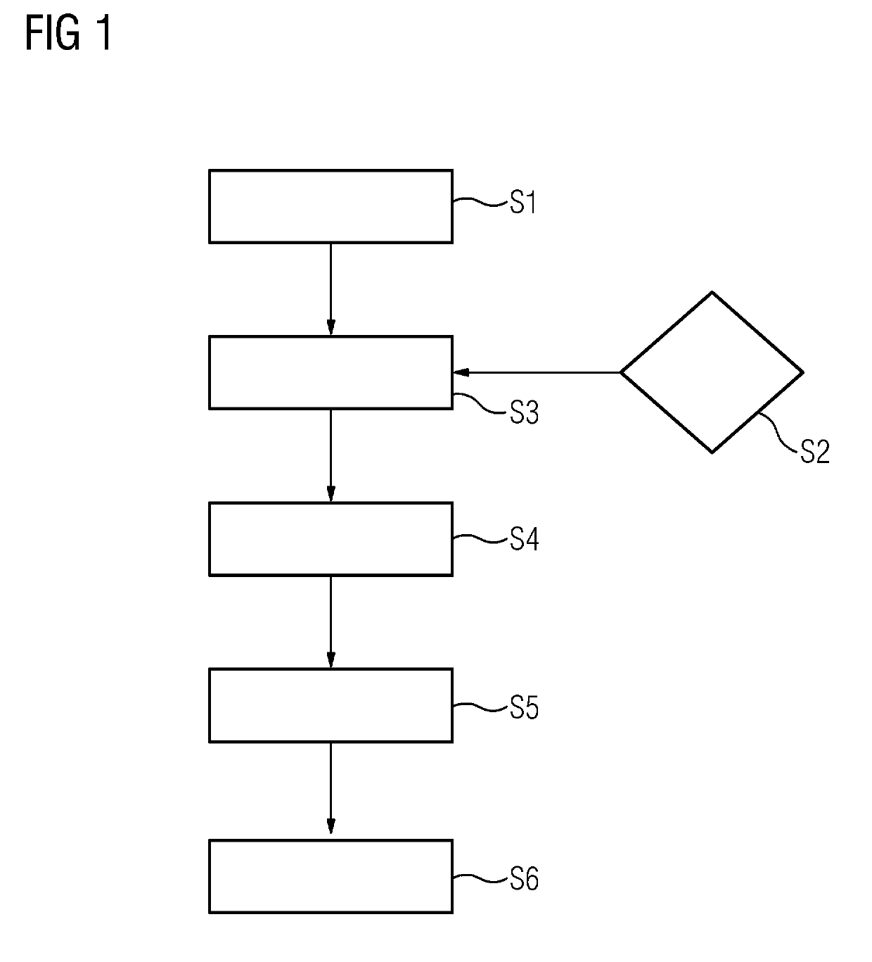
[0052]FIG. 1 shows, in the form of a flowchart, one exemplary embodiment of the steps of the method according to embodiments of the invention. The exemplary embodiment relates to a rail system comprising a switch and a switch drive. In step S1, a fault or a disruption in the system is captured by means of a detection module. For example, the fault may cause a failure of the switch controller, with the result that sensors on the switch drive detect a fall in the temporal profile of the power consumption. The detected fault comprises the failure of the switch system, for example. The sensors can also capture, for example, temperature, pressure, acceleration or voltage.

[0053]In step S2, a simulation model of the technical system comprising the switch and the associated switch drive is provided. The simulation model can be set on the basis of a configuration and / or on the basis of conditions of use and / or environmental data and / or sensor data of the technical system. In other words, set...


PUM


Abstract

A method and an apparatus for identifying faults in a computer-aided manner for a technical system including a switch and a switch drive is provided. A fault or a disruption in the switch and/or in the switch drive is detected by capturing a temporal profile of a measurement variable of the switch drive. A simulation model is provided for the technical system and a fault situation is set by means of setting values of the simulation model, wherein the setting values are assigned to the fault situation. The technical system is simulated by means of the simulation model, wherein a simulated temporal profile of the measurement variable is captured. The simulated temporal profile is compared with the temporal profile of the measurement variable of the switch drive, wherein the fault situation is assigned to the detected fault on the basis of the comparison.

Description

CROSS-REFERENCE TO RELATED APPLICATIONS[0001]This application claims priority to European application No. 18164710.8, having a filing date of Mar. 28, 2018, the entire contents of which are hereby incorporated by reference.FIELD OF TECHNOLOGY[0002]The following relates to a method and an apparatus for identifying faults in a computer-aided manner for a technical system comprising a switch and a switch drive.BACKGROUND[0003]Switches and switch drives are central elements of the route in rail traffic. To ensure an operating procedure as permanently as possible, requirements imposed on the functionality of the switch / switch drive system are generally high. Disruptions or faults in the switch and / or the switch drive can greatly restrict the operation of the rail traffic.[0004]It is known practice to monitor a rail infrastructure and to check the functionality of a switch and its drive using sensors, for example. In particular, diagnostic systems which can detect a fault in the system an...

Claims


Application Information

Patent Timeline
IPC IPC(8): B61L23/04B61L25/06B61K9/08
CPCB61L23/04B61L25/06B61K9/08G06F30/20B61L5/00B61L27/60B61L27/53
Inventor HEINRICH, CHRISTOPHBOSCHERT, STEFANSCHULZE, MICHAEL
Owner SIEMENS AG
Why Eureka
Try Eureka