
Fuselage assembly for an aircraft

Active Publication Date: 2019-10-03
AIRBUS SAS +1
View PDF4 Cites 2 Cited by
  • Summary
  • Abstract
  • Description
  • Claims
  • Application Information

AI Technical Summary

Benefits of technology

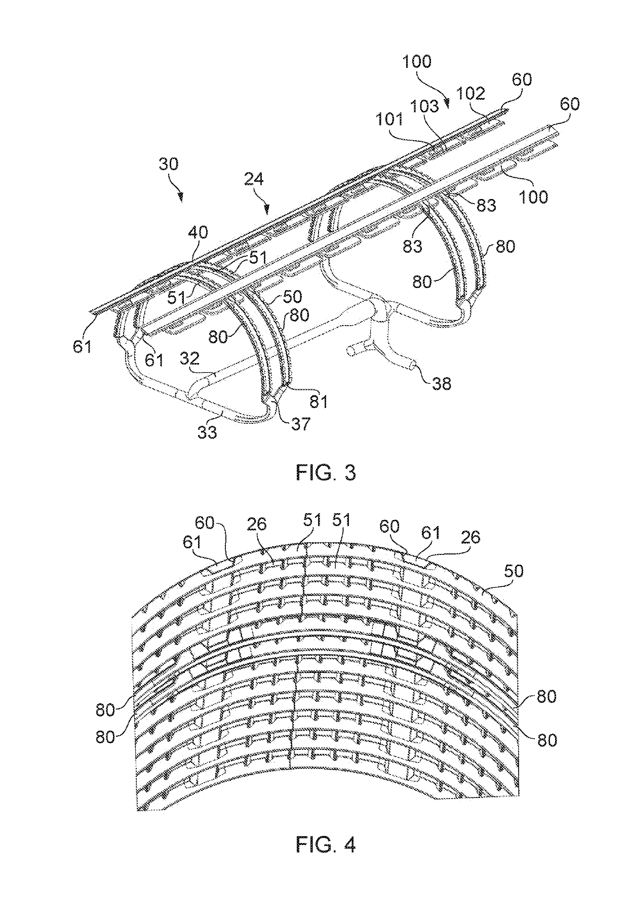
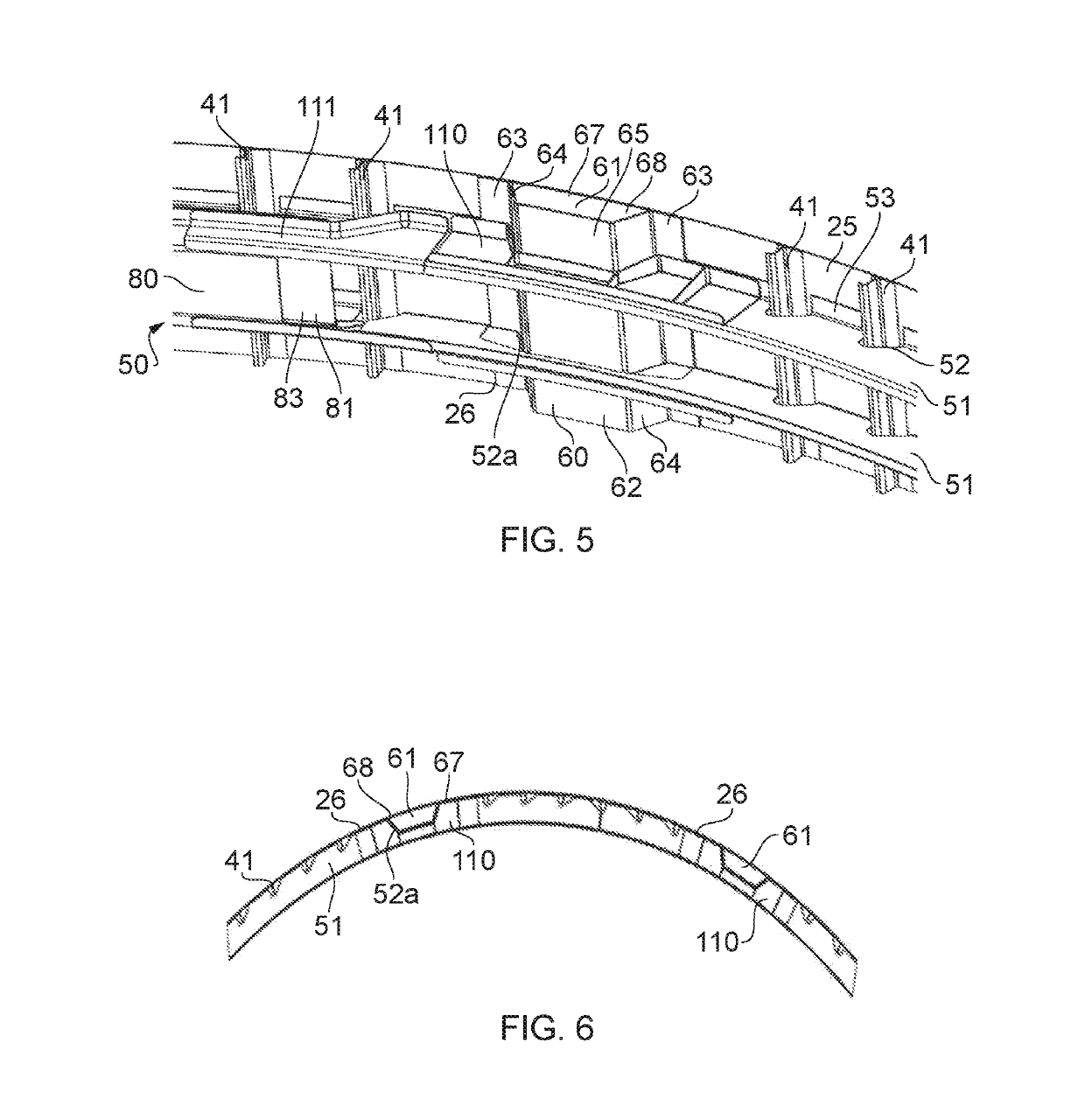
This patent talks about a way to combine the structure and air distribution system of an aircraft. This helps save space in the cabin and makes the frame stronger and lighter. The panel on the frame helps with the air distribution and also contributes to the stiffness of the frame.

Problems solved by technology

Such a cabin air distribution system therefore requires a substantive number of ducts in a complicated arrangement.

Method used


Image

  • Fuselage assembly for an aircraft
  • Fuselage assembly for an aircraft
  • Fuselage assembly for an aircraft

Examples


Embodiment Construction

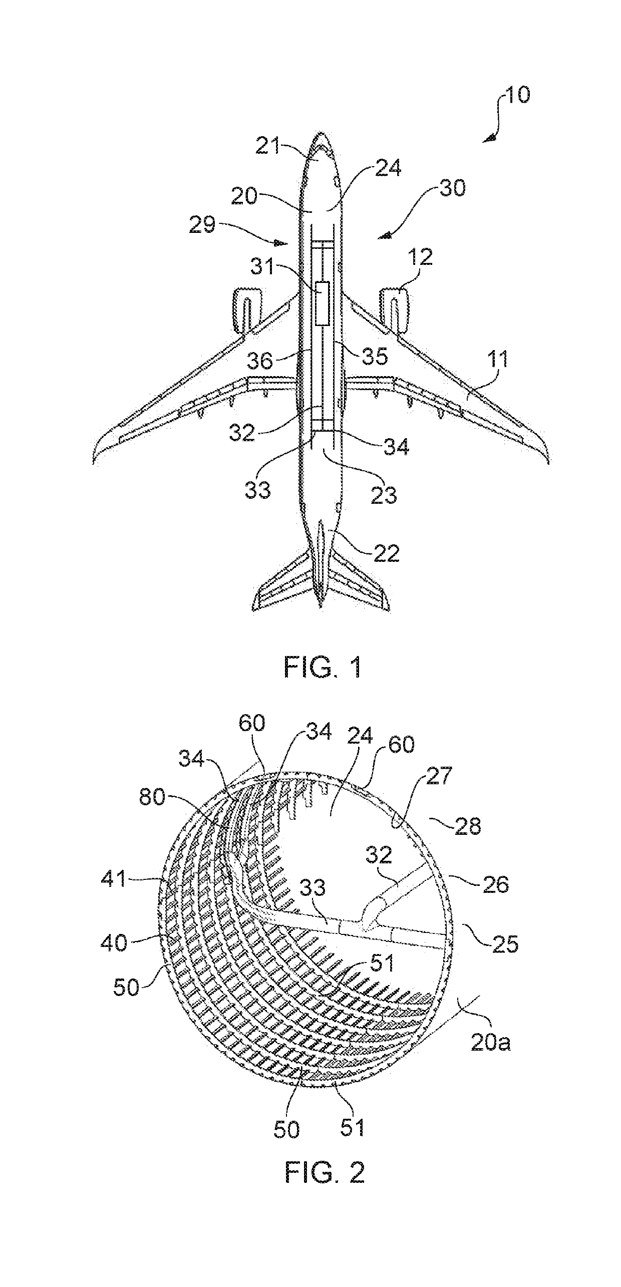
[0065]An aircraft 10 is shown in FIG. 1. The aircraft 10 includes wings 11 extending from a fuselage 20. It will be appreciated that the fuselage 20 and the wings 11 may take on a variety of different planform shapes and profiles depending on the particular application. Engines 12 are mounted to each wing 11. The fuselage 20 defines a longitudinal axis of the aircraft 10. The longitudinal axis extends from a forward end 21 to a rearward end 22.

[0066]In the following description, the term “front” refers to components towards the forward end 21, and the term “rear” refers to components towards the rearward end 22. The terms “forward” and “rearward” shall be construed accordingly. The position of features may be construed relative to other components and features, for example a forward component may be disposed on the forward side of another component, but towards the rearward end 22.

[0067]The fuselage 20 is generally tubular. The fuselage 20 is formed from one or more fuselage assembl...


PUM


Abstract

A fuselage assembly for an aircraft including a stringer extending longitudinally along the fuselage. The stringer defines a fluid channel. The fluid channel is configured to form at least part of a distribution duct of a cabin air distribution system.

Description

RELATED APPLICATION[0001]This application claims priority to Indian Patent application 201841011605 filed Mar. 28, 2018, the entirety of which is incorporated by reference.FIELD OF THE INVENTION[0002]The present invention relates to a fuselage assembly for an aircraft. The present invention also relates to a cabin air distribution system, a frame for an aircraft fuselage, and an aircraft.BACKGROUND OF THE INVENTION[0003]The fuselage of an aircraft typically has a pressurised cabin. A cabin environmental control system, also known as aircraft air-conditioning, is used to circulate airflow to the cabin. The cabin environmental control system typically takes air from one or a variety of sources, for example bleed air from an engine, recirculated air from the cabin, and atmospheric ram air which is subsequently mixed by a mixer unit and supplied to the cabin by a cabin air distribution system. A plurality of ducts are provided to supply the air from the mixer unit to the cabin.[0004]The...

Claims


Application Information

Patent Timeline
IPC IPC(8): B64C1/06B64C1/12B64C1/08B64C1/40B64D13/06
CPCB64D13/06B64C1/08B64C1/12B64C1/064B64C1/40B64D2013/0618B64C1/061B64D2013/0625
Inventor SCHROEDER, MATTHIAS S.BATANERO BENITO, JESUS MIGUELSRINIVASAN, SRIVATSYADAV, AVINASH KUMARRAMACHANDRA PATIL, VINAYAKVYAS, ABHISHEK
Owner AIRBUS SAS
Learn More