
Optical instrument comprising an entrance cavity in which a mirror is placed

an optical instrument and entrance cavity technology, applied in the direction of instruments, cosmonautic vehicles, transportation and packaging, etc., can solve the problems of not being able to compensate for orbital fluctuations, high cost and complexity, and risk of failure, so as to limit the temperature fluctuations of the cavity and the cavity, dampen the instantaneous variations, and limit the effect of the temperature fluctuations

Active Publication Date: 2010-12-21
THALES SA
View PDF13 Cites 1 Cited by
  • Summary
  • Abstract
  • Description
  • Claims
  • Application Information

AI Technical Summary

Benefits of technology

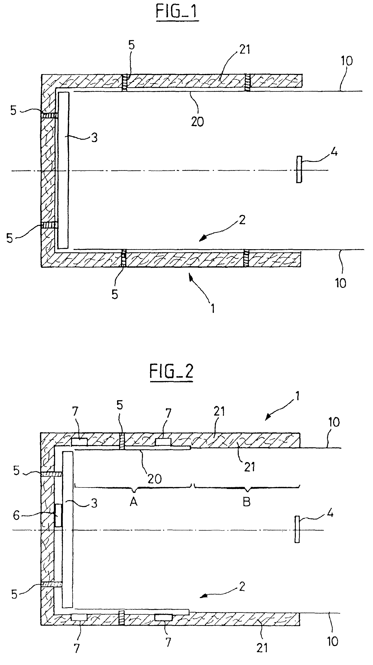
[0013]The thermal inertia of this casing, situated in the immediate vicinity of the primary mirror where the radiative exchanges are the greatest, makes it possible to limit the temperature fluctuations of the cavity and, consequently, the temperature fluctuations of the mirror.
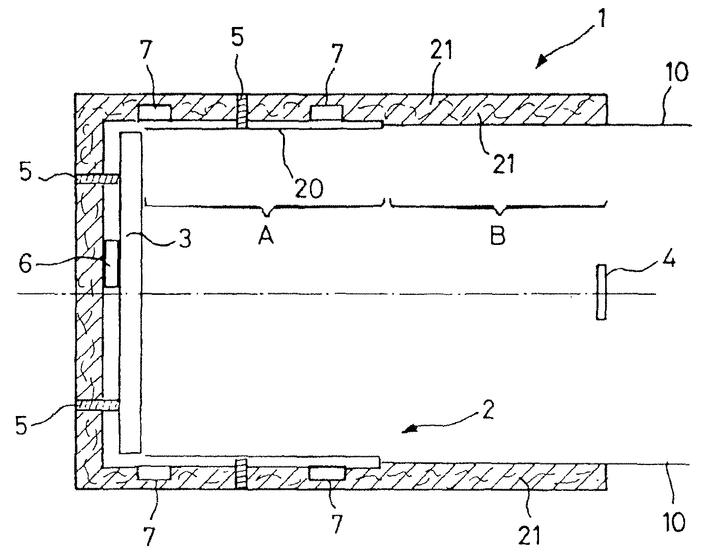
[0014]More particularly, the subject of the present invention is an optical instrument comprising at least one mirror called a primary mirror (3) placed in a cavity (2), the primary mirror comprising an active face capable of being subjected to instantaneous variations of the incident radiative flux, characterized in that the cavity comprises a rigid internal casing (20) around the mirror forming at least a portion of the cavity, this casing consisting of a material having a thermal inertia so as to dampen the instantaneous variations of the incident radiative flux thereby making it possible to limit the temperature fluctuations of this cavity and, consequently, the temperature fluctuations of the mirror.

Problems solved by technology

On the other hand, this type of regulation does not make it possible to compensate for the orbital fluctuations in the context of a satellite in low Earth orbit, because of the purely radiative mode of exchange between the heaters and the mirror.
Other solutions, of the active optical type, exist but are costly and complex to apply because of the use of dedicated electronics and complex functional tests on the ground, and they have a risk of failure.
A direct thermal regulation of the active face would make it possible to obtain an equivalent level of stability of the mirror, but this solution is, to the knowledge of the applicant, not achieved and would present risks of thermoelastic deformation.

Method used


Image

  • Optical instrument comprising an entrance cavity in which a mirror is placed
  • Optical instrument comprising an entrance cavity in which a mirror is placed

Examples


Embodiment Construction

[0027]The instrument 1 described comprises a cavity 2 making it possible to receive the mirror 3, called the primary mirror, and to attach it to the instrument by conventional attachment means 5. Usually, the mirror is in a tubular cavity with a diameter slightly greater than its own so as to come on the periphery of this mirror. The mirror 3 is centered in the cavity and its active face is turned toward the entrance of the cavity, the place for the location of a secondary mirror 4.

[0028]In the prior art, the cavity is made by a thermal insulation casing made by an insulation cover called MLI (Multi-Layered Insulation) painted black on the inside of the cavity and having great temperature variations.

[0029]Rather than using a conventional insulation casing, the proposed solution consists in using an entrance cavity for the optical instrument 1 having a great thermal inertia. For this, the cavity 2 comprises at least one portion made of a material with high inertia with respect to the...


PUM


Abstract

The invention relates to an optical instrument (1) comprising at least one mirror called the primary mirror (3), placed in a cavity (2) and comprising an active face capable of being subjected to instantaneous variations of the incident radiative flux. According to the invention, the cavity (2) comprises a rigid internal casing (20) around the mirror consisting of a material having a thermal inertia so as to damp the instantaneous variations of the incident radiative flux thereby making it possible to limit the temperature fluctuations of this cavity and, consequently, the temperature fluctuations of the mirror. The invention applies to the space field.

Description

CROSS-REFERENCE TO RELATED APPLICATIONS[0001]The present application is based on International Application No. PCT / FR2006 / 051234, filed on Nov. 27, 2006, which in turn corresponds to French Application No. 0553620, filed on Nov. 28, 2005, and priority is hereby claimed under 35 USC §119 based on these applications. Each of these applications are hereby incorporated by reference in their entirety into the present application.FIELD OF THE INVENTION[0002]The invention relates to an optical instrument comprising an entrance cavity in which a mirror called the primary mirror is placed.BACKGROUND OF THE INVENTION[0003]The invention applies to any optical instrument comprising a mirror requiring a very great thermal stability, in order to limit the thermoelastic deformations, in particular over short periods, for example one to two hours.[0004]The invention applies most particularly but not exclusively to the optical instruments used in the space field such as the optical instruments on bo...

Claims


Application Information

Patent Timeline
Patent Type & Authority Patents(United States)
IPC IPC(8): G02B23/16
CPCG02B7/181
Inventor CHANAL, OLIVIERVALENTINI, DAVIDDEVILLIERS, CHRISTOPHE
Owner THALES SA
Learn More