
Image forming apparatus controlling power supplied to fixing unit

a technology of fixing unit and forming apparatus, which is applied in the direction of electrographic process apparatus, instruments, optics, etc., can solve the problems of low harmonic current but, high flicker noise, and low flicker noise but, and achieve the effect of reducing the gloss unevenness of an imag

Inactive Publication Date: 2014-10-28
CANON KK
View PDF36 Cites 0 Cited by
  • Summary
  • Abstract
  • Description
  • Claims
  • Application Information

AI Technical Summary

Benefits of technology

[0013]The present invention has been made under circumstances such as described above, and is to control temperature fluctuation of a heating nip portion following entry of a printing material, and to reduce gloss unevenness of an image on the printing material.

Problems solved by technology

Wave number control characteristically results in low harmonic current but high flicker noise, since the power supply rate is controlled every prescribed period of several waves.
On the other hand, phase control characteristically results in low flicker noise but high harmonic current, since the power supply rate can be finely controlled within individual half waves.
Incidentally, when, in the case where wave number control is used with a fixing apparatus employing the film heating method, the power supply is often OFF at the leading edge portion of the printing material because of wave number control resulting in power supply being turned ON / OFF in units of half waves, fixing failure will occur due to the temperature of the heater suddenly dropping.
Also, with a fixing apparatus employing the film heating method, particularly a fixing apparatus in which the heating film is provided with an elastic layer, the heating state of the printing material will be destabilized due to the printing material entering the heating nip portion.
This is caused by the large fluctuation in temperature that occurs in the heating nip portion due to the heating film temperature suddenly dropping because of heat suddenly being absorbed by the printing material when the printing material enters the stable temperature state, and the overshoot that arises when the temperature subsequently increases.
Since the glossiness of printing material such as glossy paper in particular is extremely sensitivity to temperature, and very slight differences in temperature appear as a difference in gloss level, the range within which surface temperature should be controlled is very limited.
When the power correction timing deviates even slightly from the proper correction timing, either there will be insufficient power to be able to fully compensate for the temperature drop or a hot offset or the like will occur due to excessive power input, weakening the effect of the power correction.
Also, with a fixing apparatus employing wave number control, there is a problem in that temperature fluctuation due to entry of the printing material cannot be adequately reduced because correction cannot be performed at the timing at which power correction should be performed in response to entry of the printing material.
Since wave number control has a long power supply rate update period, the timing at which power correction is actually performed may deviate significantly from the proper power correction timing.
As shown in FIG. 9B, when power correction is performed before the proper timing, the temperature of the heating nip portion will rise too much and overheat.
When the printing material carrying the toner image enters the overheated heating nip portion, the toner becomes excessively fused and hot offset occurs.
Also, since a large amount of power is supplied earlier than the proper timing, the temperature of the heating film becomes too high before entry of the printing material, and the gloss of the printing material increases at the trailing edge portion of the first rotation of the film.
9C, it will be impossible to compensate for the reduction in heat caused by entry of the printing material, and the temperature of the heating film will drop significantly.
In this case, the gloss of the leading edge portion of the second rotation of the heating film will be too low, resulting in gloss unevenness in which the difference in gloss level between the trailing edge portion of the first rotation and the leading edge portion of the second rotation is clearly apparent.
To cope with this problem, the update period of the power supply rate can conceivably be shortened, for example, but since the wave number of the update period decreases in this case, the power supply rate cannot be finely set, giving rise to problems with temperature control.

Method used


Image

  • Image forming apparatus controlling power supplied to fixing unit
  • Image forming apparatus controlling power supplied to fixing unit
  • Image forming apparatus controlling power supplied to fixing unit

Examples


embodiment 1

Overview of Image Forming Apparatus

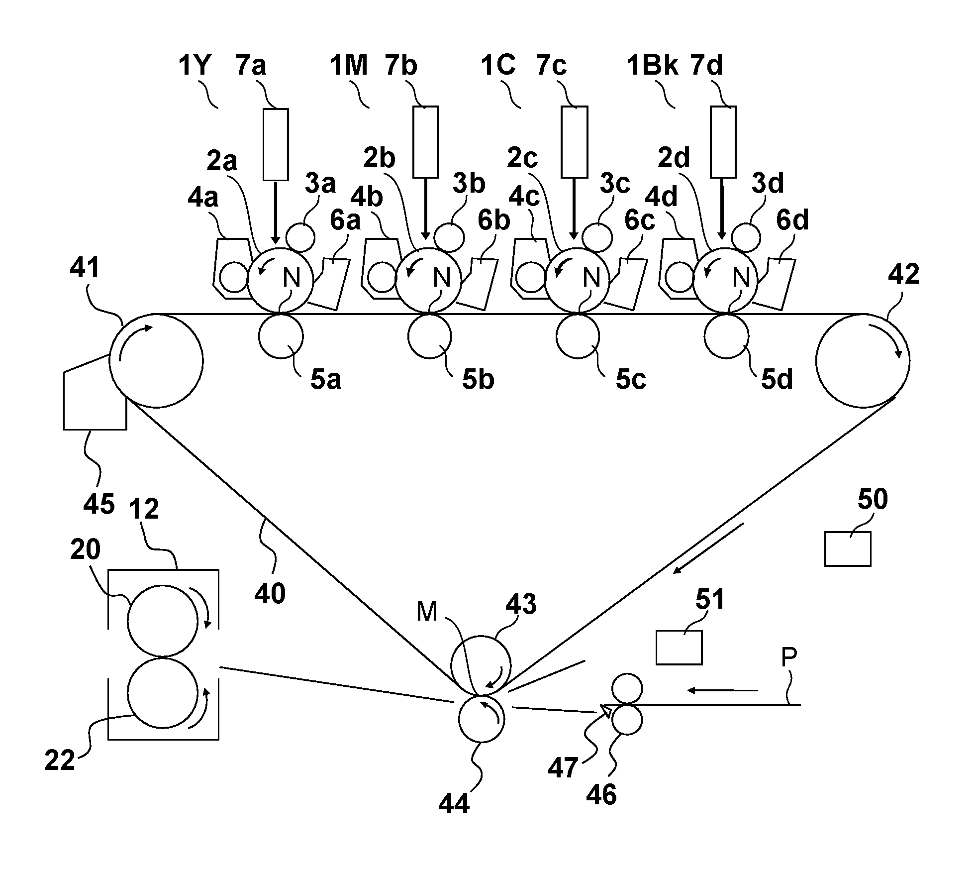
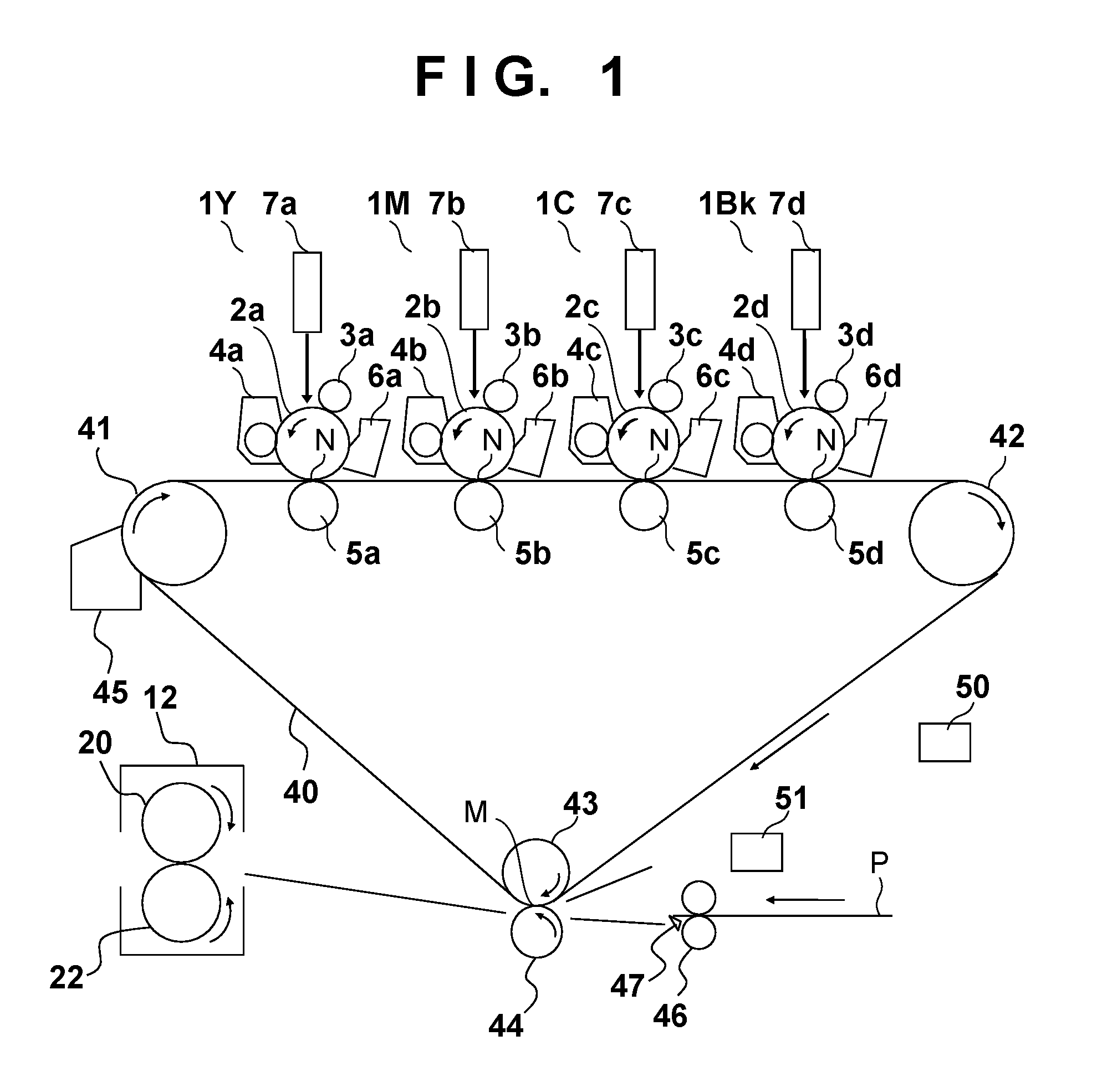
[0030]FIG. 1 is a cross-sectional view showing the configuration of a color image forming apparatus of the present embodiment. This color image forming apparatus is a tandem full-color printer employing an electrophotographic method. The color image forming apparatus is provided with four image forming units, namely, an image forming unit 1Y that forms a yellow image, an image forming unit 1M for magenta, an image forming unit 1C for cyan, and an image forming unit 1Bk for black, which are disposed in a row at fixed intervals. Photosensitive drums 2a, 2b, 2c, and 2d are respectively installed in the image forming units 1Y, 1M, and 1C and 1Bk (hereinafter, simply referred to as image forming units 1). The letters a, b, c and d respectively correspond to Y (yellow), M (magenta), C (cyan) and Bk (black), and hereinafter will be abbreviated as a˜d (or a, b, c and d) unless otherwise required. A charging roller 3, a developing apparatus 4, a transfer ro...

embodiment 2

[0084]In Embodiment 1, the power supply rate update timing and the power correction start timing were made to coincide, by adjusting the image forming start timing based on the power supply rate update timing. The power correction start timing is determined based on the entry timing of the printing material P to the heating nip portion H, with the entry timing of the printing material P to the heating nip portion H being predicted using the conveyance start timing of the printing material P by the registration roller 46 as a basis in the present embodiment. Since the conveyance start of the printing material P can be accurately detected with operation of the registration roller 46, the power correction timing can be determined using the conveyance start timing of the printing material P as a basis, regardless of the image forming start timing. Accordingly, it can be said that adjusting the conveyance start timing of the printing material P based on the power supply rate update timin...


PUM


Abstract

Adjusting the start timing for conveying a printing material from a printing material conveying unit based on a power supply update period for power supplied to a heater allows proper power correction timing to be attained for compensating for a drop in temperature of the endless belt following the printing material entering a fixing nip portion.

Description

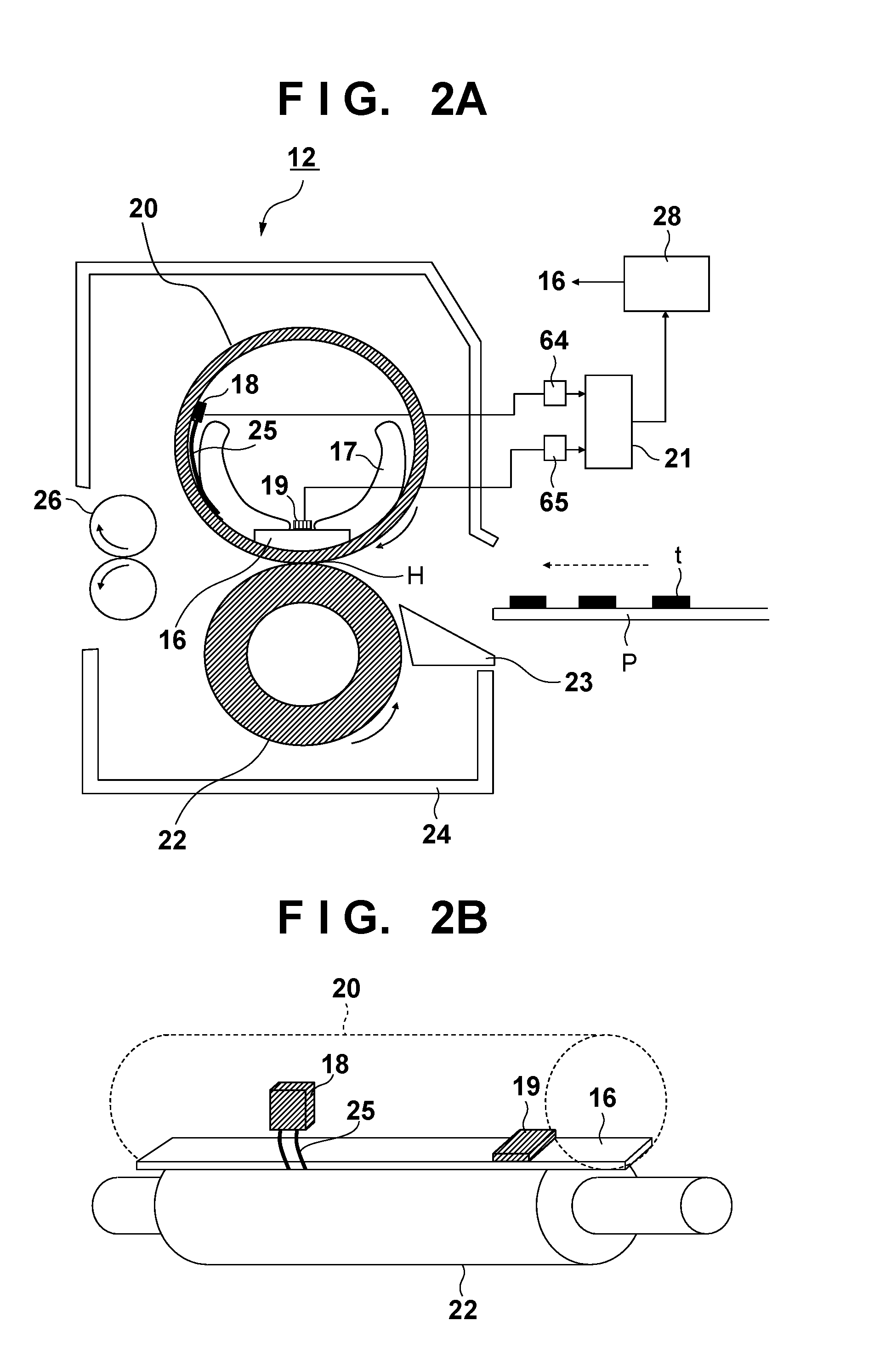
BACKGROUND OF THE INVENTION[0001]1. Field of the Invention[0002]The present invention relates to an image forming apparatus utilizing an electrophotographic process or the like.[0003]2. Description of the Related Art[0004]Heretofore, image forming apparatuses such as copiers and printers that use an image forming process such as an electrophotographic process, an electrostatic recording process or a magnetic recording process, for example, have been provided with a fixing apparatus for using heat to fuse and fix an unfixed toner image on printing material. As for fixing apparatuses for printing material, in terms of method and configuration, apparatuses that employ a heat roller method, a heat plate method, a heat chamber method and a film heating method are known. Fixing apparatuses all incorporate a heating body, and temperature control is managed by controlling power supply to the heating body, such that the temperature of the heating body is maintained at a prescribed temperatur...

Claims


Application Information

Patent Timeline
Patent Type & Authority Patents(United States)
IPC IPC(8): G03G15/20
CPCG03G2215/2016G03G15/657G03G15/2003G03G15/2082G03G15/2078G03G15/205G03G2215/2032G03G15/2039G03G15/2042
Inventor FUKUZAWA, DAIZOKURATA, MUNEHITOSATO, NORIAKIKASUGA, KUNIAKIYOSHIOKA, MAHITO
Owner CANON KK
Learn More