
Aircraft nacelle with rotary fan cowling incorporating an access hatch

Active Publication Date: 2019-10-03
AIRBUS OPERATIONS (SAS)
View PDF0 Cites 2 Cited by
  • Summary
  • Abstract
  • Description
  • Claims
  • Application Information

AI Technical Summary

Benefits of technology

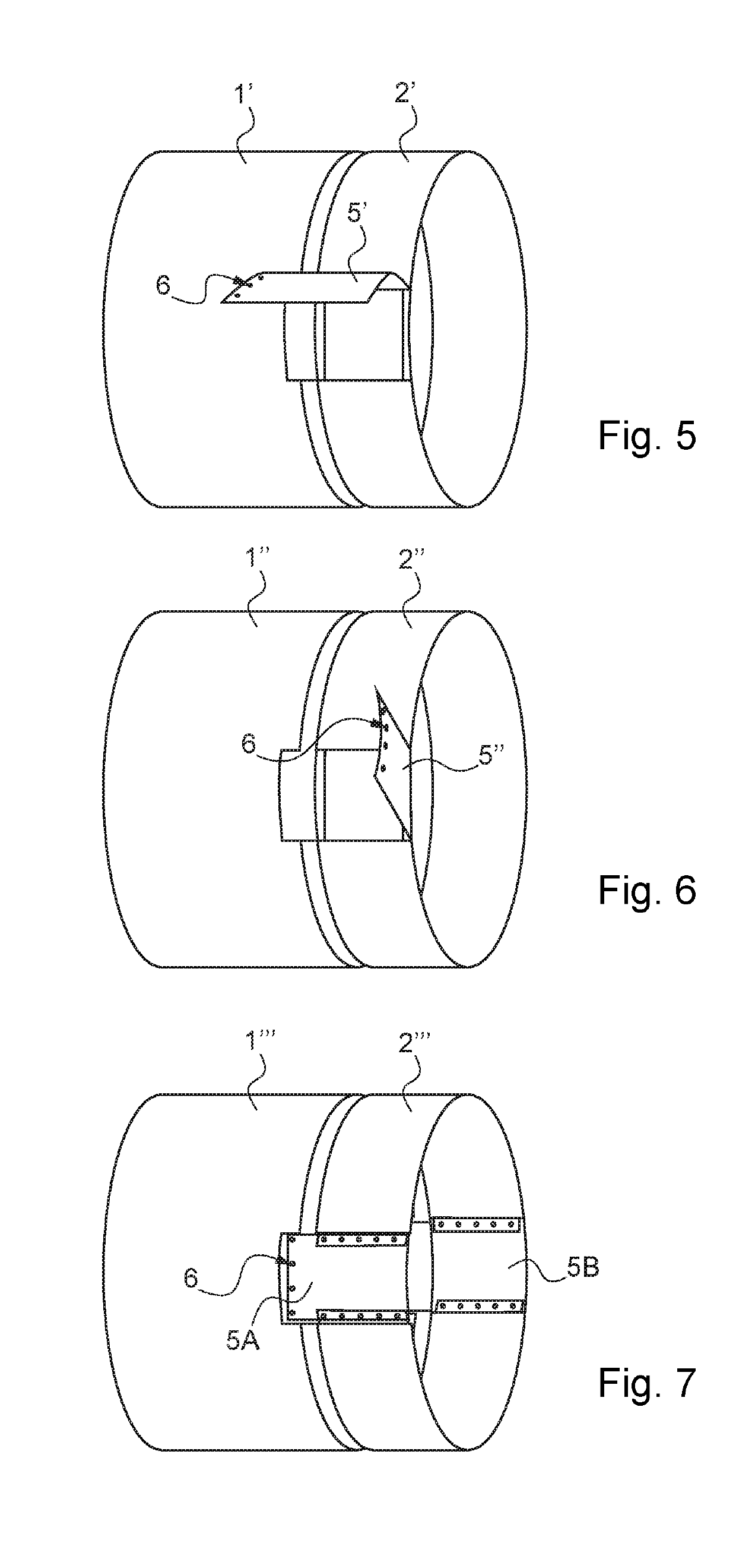
The invention relates to a fan cowling for an aircraft engine that has access openings closed by hatches. The fan cowling can be positioned to provide access to different parts of the engine by rotating around the nacelle. The attachment of the fan cowling to the air inlet can be done over all its length or at certain points to limit deformations and scooping. The use of ball joints made of carbon-based composite material can provide benefits such as self-lubrication. The invention is not limited to the specific forms of the circular rail and the runner, and a variation where the runner extends over all the length of the circular rail can be used but has a slightly higher mass.

Problems solved by technology

Furthermore, this wind resistance limits the maintenance operations to light wind conditions (wind speed below a certain value).
These problems are, in addition, aggravated by the current trend to increase the diameters of the nacelle.
Another consequence of the increase in the diameter of the nacelles is to reduce the space available between the nacelle and the ground and therefore to render the access to the fan cowling closure systems more difficult for the operator.
Finally, an additional difficulty arises in the case of certain types of recent engines or engines in development, particularly in the case of the engines of UHBR (Ultra High Bypass Ratio) type.
This length reduction is incompatible with the known, butterfly opening mounting systems.
The reduction of the size of the butterfly opening cowling portions in the nacelle of FR 3 036 382, compared to the nacelles equipped only with two butterfly opening half-cowlings (that is to say, with no third, bottom cowling portion), makes it possible to limit the amplitude of the deformation of the butterfly opening cowling portions but does not completely resolve this problem.

Method used


Image

  • Aircraft nacelle with rotary fan cowling incorporating an access hatch
  • Aircraft nacelle with rotary fan cowling incorporating an access hatch
  • Aircraft nacelle with rotary fan cowling incorporating an access hatch

Examples


Embodiment Construction

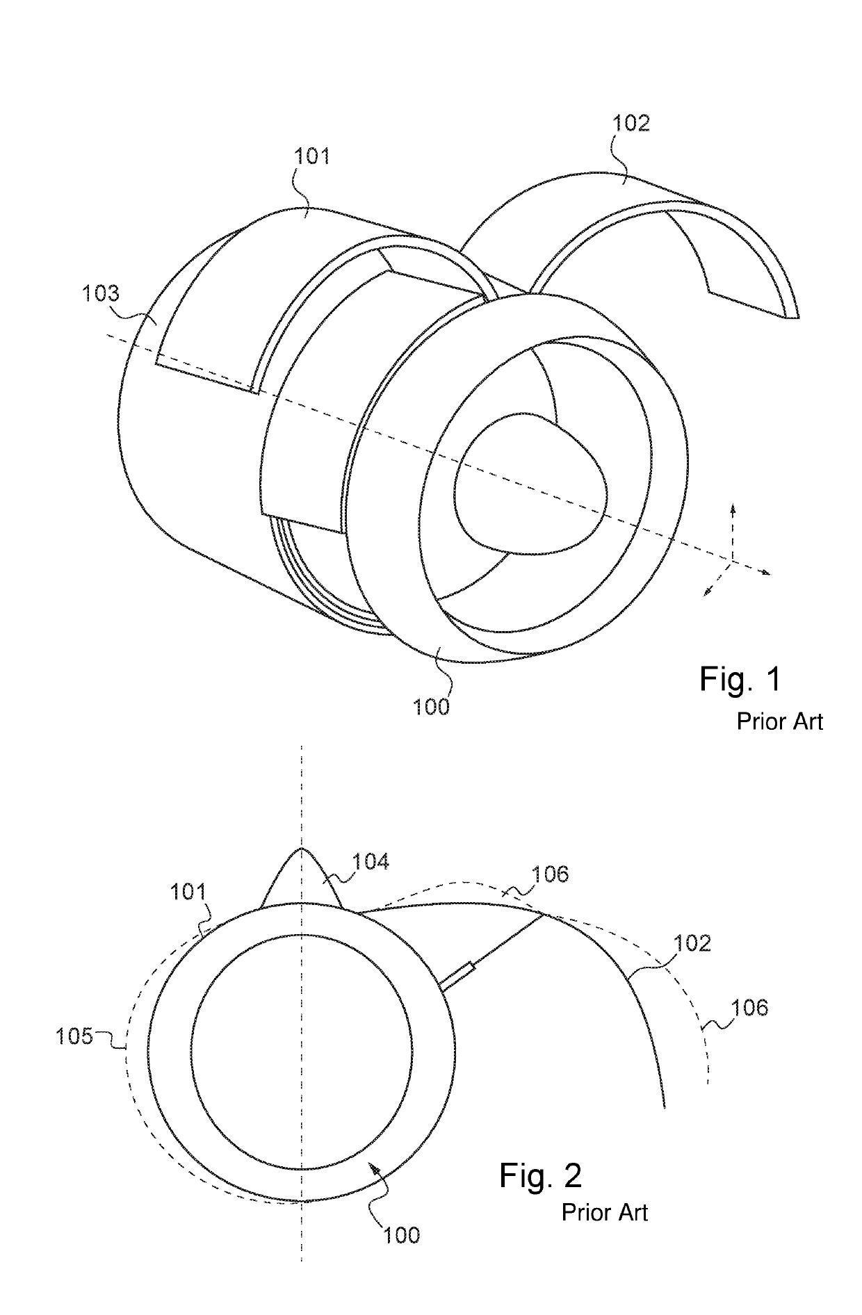
[0058]FIGS. 1 and 2 relate to nacelles having a butterfly opening fan cowling according to the prior art. They have been described in the Background section. FIG. 2 illustrates, in particular, the deformations that the earlier fan cowlings undergo in flight when the fan cowling is closed (left-hand part of the figure) and on the ground when the fan cowling is open (right-hand part of the figure).

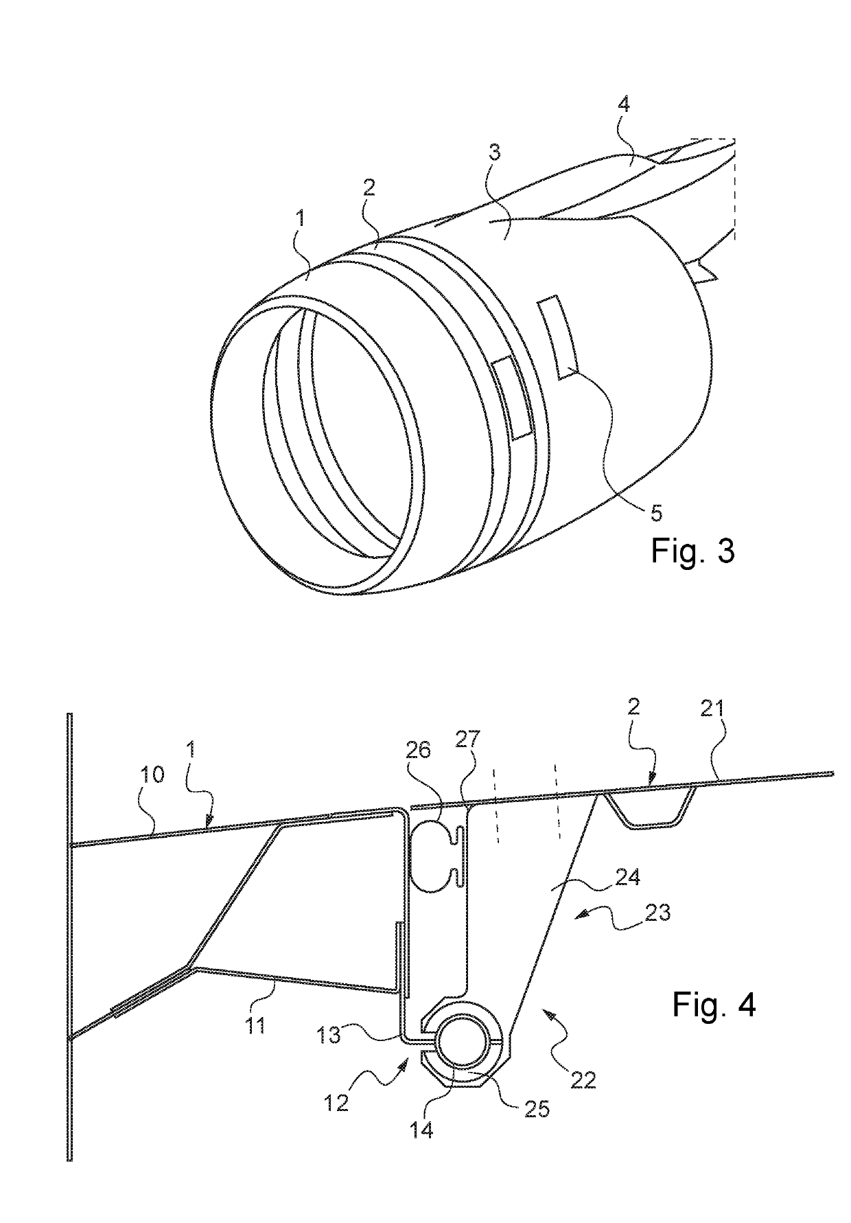
[0059]The nacelle according to the invention, illustrated in FIGS. 3 and 4, comprises an air inlet 1, a fan cowling 2, and a downstream portion 3 having a thrust reversing zone. The assembly is borne by a pylon 4. Normally (see FIG. 4), the air inlet 1 comprises, among other things, an outer wall 10 and a frame 11, and the fan cowling comprises an outer wall 21 in the extension of the outer wall 10 of the air inlet.

[0060]According to the invention, the fan cowling 2 is mounted to rotate about the central axis of the nacelle relative to the air inlet 1 (and to the downstream portion 3). To th...


PUM


Abstract

An aircraft nacelle comprising an air inlet, with a single fan cowling made of a single piece which extends over all the circumference of the fan. The fan cowling is borne by the air inlet and is mounted to be rotationally mobile about the axis of the nacelle relative to the air inlet, via a link and guiding arrangement comprising a circular rail and a runner capable of sliding along the circular rail. The fan cowling comprises one or more openings closed by hatches allowing access to the interior of the nacelle. The fan cowling has little susceptibility to being deformed both in flight and on the ground during maintenance operations. Furthermore, no pylon portion is needed in the zone of the fan cowling since the latter is not attached to the pylon.

Description

CROSS-REFERENCES TO RELATED APPLICATIONS[0001]This application claims the benefit of the France patent application No. 1852742 filed on Mar. 29, 2018, the entire disclosures of which are incorporated herein by way of reference.FIELD OF THE INVENTION[0002]The invention relates to an aircraft nacelle.BACKGROUND OF THE INVENTION[0003]An aircraft nacelle is a fairing which surrounds an engine in an aircraft; it is attached to an engine pylon, and its main functions are to support and protect the engine. Conventionally, a nacelle comprises, from front to rear, a first section upstream of the aerodynamic flow, called an air inlet, a second section which covers the casing of the engine fan, called a fan cowling, and a third section which generally has a thrust-reversing zone which surrounds the turbine body of the engine downstream of the aerodynamic flow.[0004]The fan cowling fulfils several functions, including a function of protection of the engine and a function of continuity of the ae...

Claims


Application Information

Patent Timeline
IPC IPC(8): B64D29/06B64D29/08
CPCB64D29/06B64D29/08B64C7/02
Inventor PORTE, ALAINPONS, FRANÇOISALBET, GREGORY
Owner AIRBUS OPERATIONS (SAS)
Learn More