Unlock instant, AI-driven research and patent intelligence for your innovation.

Projection type display device, control method of projection type display device, control program of projection type display device

Inactive Publication Date: 2019-10-03
FUJIFILM CORP
View PDF3 Cites 2 Cited by
  • Summary
  • Abstract
  • Description
  • Claims
  • Application Information

AI Technical Summary

Benefits of technology

The present invention aims to provide a progression type display device and control method for it that can fix the position of a combiner to a desired position to make it easier for operators to use without adding burden.

Problems solved by technology

For this reason, there is a problem in that the operation for the lock release is complicated.
Even in a case where a so-called electromagnetic lock that electrically controls a locking mechanism is employed, it is necessary for a user to send an intention of lock release to a system through an operation of an operating button, or the like, and thus, it is difficult to solve inconvenience of an operation of the lock release.
In this case, release of the locking mechanism is complicated.
A configuration in which lock by a locking mechanism is released in an electrically driven manner in accordance with start-up of the HUD may be considered, but in this case, during the start-up of the HUD, it is not possible to lock the combiner at the withdrawal position, or it is necessary to perform an operation of locking the combiner at the withdrawal position.

Method used


Image

  • Projection type display device, control method of projection type display device, control program of projection type display device
  • Projection type display device, control method of projection type display device, control program of projection type display device
  • Projection type display device, control method of projection type display device, control program of projection type display device

Examples


Embodiment Construction

[0026]Hereinafter, embodiments of the invention will be described with reference to the accompanying drawings.

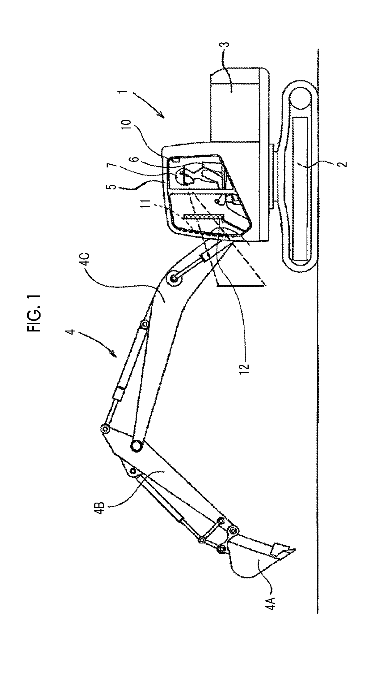
[0027]FIG. 1 is a schematic diagram showing a configuration of a construction machine 1 in which an HUD 100 that is a projection type display device according to a first embodiment of the invention is mounted.

[0028]The construction machine 1 is a hydraulic excavator, which includes respective parts of a lower traveling body 2, an upper revolving body 3 that is supported to be rotatable on the lower traveling body 2, a front working part 4 that is supported by the upper revolving body 3, and the like. The lower traveling body 2 and the upper revolving body 3 form a main part of the construction machine 1.

[0029]The lower traveling body 2 includes a metallic or rubber crawler for traveling a public road and a workplace.

[0030]The upper revolving body 3 includes an operator cab 5 in which an operating device for operating the front working part 4 and a cab seat 6 on which an oper...


PUM


Abstract

Provided are a projection type display device, a control method of a projection type display device, and a control program of a projection type display device, capable of fixing a position of a combiner to a desired position to enhance usability without imposing a burden on an operator of a working machine. An HUD 100 includes a rotating part 15A that supports the combiner 12 to be rotatable between an in-use position and a withdrawal position, a locking mechanism 15B that prohibits rotation of the combiner 12, and a projection display section 50 that spatially modulates light emitted from a light source on the basis of image information, and projects image light obtained through the spatial modulation onto a projection surface 12A of the combiner 12 to display an image based on the image light, a locking mechanism controller 63 that controls the locking mechanism 15B on the basis of a traveling state of a construction machine 1 or an operating state of a bucket 4A.

Description

CROSS REFERENCE TO RELATED APPLICATION[0001]This is a continuation of International Application No. PCT / JP2017 / 037549 filed on Oct. 17, 2017, and claims priority from Japanese Patent Application No. 2016-248119 filed on Dec. 21, 2016, the entire disclosures of which are incorporated herein by reference.BACKGROUND OF THE INVENTION1. Field of the Invention[0002]The present invention relates to a projection type display device, a control method of the projection type display device, and a computer readable medium storing a control program of the projection type display device.2. Description of the Related Art[0003]A vehicle head-up display (HUD) that projects, using a combiner disposed in the vicinity of a windshield of a vehicle such as an automobile, a train, a ship, a construction machine, an aircraft, or an agricultural machine, as a screen, light onto the screen to display an image is known (see JP2005-297619A, JP2006-248323A, JP2006-279800A, and JP2001-051228A). According to the ...

Claims


Application Information

Patent Timeline
IPC IPC(8): G02B27/01B60K35/00E02F9/26H04N9/31
CPCH04N9/3111G02B27/0149H04N9/312G02B2027/0159B60K2370/66B60K2370/172B60K2370/1529E02F9/26B60K35/00B60K2370/52B60R11/02G09F9/00H04N9/3194H04N9/3141G02B2027/0156G03B29/00G03B21/58B60K35/23B60K35/28B60K2360/177B60K2360/66B60K35/22B60K35/53G02B27/01H04N5/74B60K35/81B60K2360/172
Inventor OSHIMA, HIROYUKI
Owner FUJIFILM CORP