Methods to selectively embed magnetic materials in substrate and corresponding structures

a technology of magnetic materials and substrates, applied in the field of electromechanical packaging, can solve the problems of negatively interacting processing environments with magnetic fillers, reducing bath life and chemistry performance,

Active Publication Date: 2019-10-03
INTEL CORP
View PDF0 Cites 3 Cited by
  • Summary
  • Abstract
  • Description
  • Claims
  • Application Information

AI Technical Summary

Problems solved by technology

However, substrate manufacturing process used today for integrating magnetic material into the package lead to interactions with wet chemistries such as desmear, electroless plating, flash etch, soft etch, surface finishes, and the like.
In particular, processing environments interact negatively with the magnetic fillers (e.g., Fe fillers).
For example, the processing environment may interact with the magnetic materials and result in corrosion.
Additionally, the magnetic fillers may leach into the chemistry bath and reduce the bath life and chemistry performance.

Method used


Image

  • Methods to selectively embed magnetic materials in substrate and corresponding structures
  • Methods to selectively embed magnetic materials in substrate and corresponding structures
  • Methods to selectively embed magnetic materials in substrate and corresponding structures

Examples


example 2

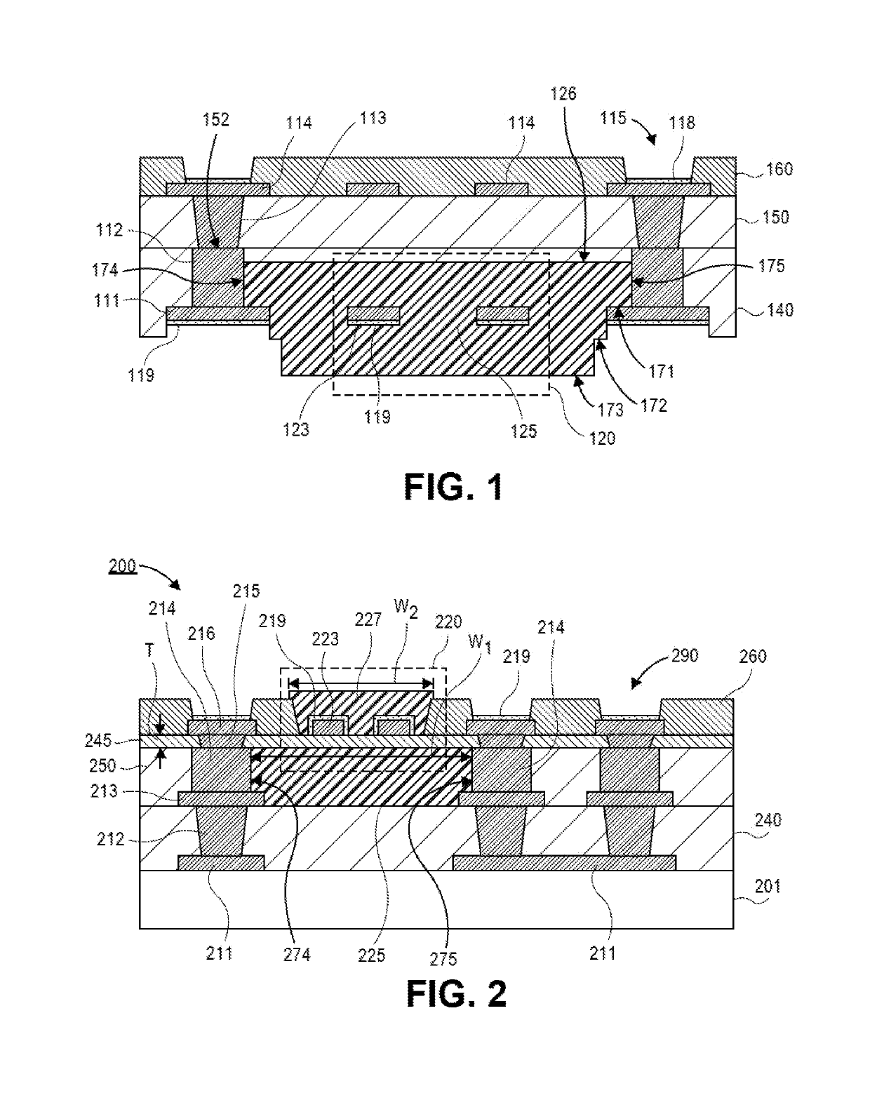
[0072 includes the inductor of Example 1, wherein the inductor is integrated into a package substrate.

[0073]Example 3 includes the inductor of Example 1 or Example 2, further comprising: pillars embedded within the package substrate, wherein the magnetic body contacts surfaces of the pillars.

[0074]Example 4 includes that inductor of Example 1-3, further comprising: a first conductive layer contacting a surface of each of the pillars, wherein the first step surface is substantially coplanar with a surface of the first conductive layer.

[0075]Example 5 includes that inductor of Example 1-4, wherein the first conductive layer is substantially the same thickness as the inductor trace.

[0076]Example 6 includes that inductor of Example 1-5, wherein the pillars have substantially vertical sidewalls.

[0077]Example 7 includes that inductor of Example 1-6, wherein a surface of the inductor trace is substantially coplanar with first surfaces of the pillars.

[0078]Example 8 includes that inductor o...

example 11

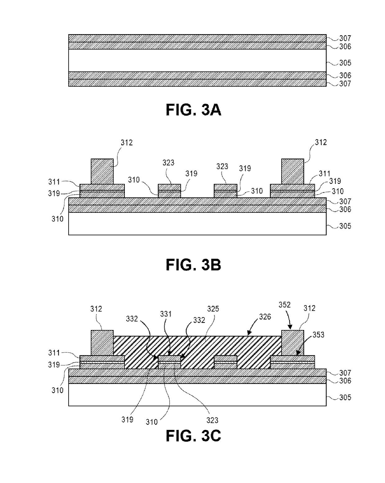
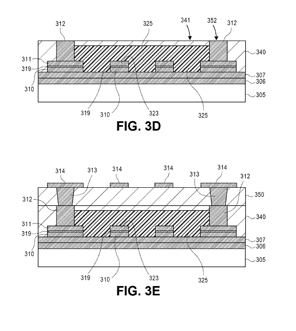
[0081 includes the inductor of Example 10, wherein sidewalls of the second magnetic body are substantially vertical.

example 12

[0082 includes the inductor of Example 10 or Example 11, wherein sidewalls of the second magnetic body include a stepped surface.

[0083]Example 13 includes the inductor of Example 10-12, wherein sidewalls of the first magnetic body are tapered.

[0084]Example 14 includes the inductor of Example 10-13, wherein the barrier layer is less than approximately 5μm.


PUM

PropertyMeasurementUnit
thicknessaaaaaaaaaa
thicknessaaaaaaaaaa
conductiveaaaaaaaaaa

Abstract

Embodiments include an inductor that comprises an inductor trace and a magnetic body surrounding the inductor trace. In an embodiment, the magnetic body comprises a first step surface and a second step surface. Additional embodiments include an inductor that includes a barrier layer. In an embodiment, an inductor trace is formed over a first surface of the barrier layer. Embodiments include a first magnetic body over the inductor trace and the first surface of the barrier layer, and a second magnetic body over a second surface of the barrier layer opposite the first surface. In an embodiment, a width of the second magnetic body is greater than a width of the first magnetic body.

Description

TECHNICAL FIELD[0001]Embodiments of the present disclosure relate to electronics packaging, and more particularly, to electronics packaging with embedded magnetic material to form passive devices.BACKGROUND[0002]Improvement in power delivery is needed in packaging architectures in order to meet increasingly demanding electrical requirements. Furthermore, the improvement in power delivery needs to be implemented without increasing the form factor (e.g., the Z-height) of packages. One way to obtain the desired improvements in power delivery is by utilizing magnetic materials on coreless substrates.[0003]However, substrate manufacturing process used today for integrating magnetic material into the package lead to interactions with wet chemistries such as desmear, electroless plating, flash etch, soft etch, surface finishes, and the like. In particular, processing environments interact negatively with the magnetic fillers (e.g., Fe fillers). For example, the processing environment may i...

Claims


Application Information

Patent Timeline
Patent Type & Authority Applications(United States)
IPC IPC(8): H01F27/28H01F27/24H01F27/02
CPCH01F27/2804H01F27/24H01F27/022H01F27/2847H01L23/3107H01L21/56H01F17/0006H01F2017/0066H01F41/046H01L2224/16225H01L2924/15311H01F17/02H01F17/04H01F17/0033H01L28/10H01L23/12H01L23/481H01L24/14H01F2017/0073H01F2017/004H05K1/185H05K2201/10
Inventor XU, CHENGLEE, KYU-OHZHAO, JUNNANJAIN, RAHULPARK, JI YONGVADLAMANI, SAIKIM, SEO YOUNG
Owner INTEL CORP
Why Eureka
Try Eureka