Panaoramic vision system with parallax mitigation

a vision system and parallax technology, applied in the field of panoramic vision systems, can solve problems such as excessive latency in real-time applications

Active Publication Date: 2019-10-03
HONEYWELL INT INC
View PDF7 Cites 2 Cited by
  • Summary
  • Abstract
  • Description
  • Claims
  • Application Information

AI Technical Summary

Benefits of technology

[0035]Not only is the processor 108 configured to adjust the first, second, third, and fourth predetermined snap angles based on the elevation position signal, it is also configured, in a least some embodiments, to linearly reduce the adjustments to the first, second, third, and fourth predetermined snap angles based additionally on the azimuth position signal. This is because, even though the snaps between image sensors 102 at the predetermined snap angles was quite clean, there was an offset in the images supplied from the second and third image sensors 102-2, 102-3. It has been found that this offset can be mitigated by linearly bleeding off the offset such that it is dissipated at the center azimuth angle of each of the image sensors 102. If the viewer's head 126 is rotated azimuthally back toward the associated predetermined snap angle without going to the bleed off limit, then the residual angle is adjusted out in the snap back to the other image sensor 102. It will be appreciated that bleed off may be dissipated at an arbitrary angle between the center azimuth and the snap angle, and not just the center azimuth, as in the described embodiment.

Problems solved by technology

Although this technique is fairly accurate, the processing time associated with generating the depth fields results in excessive latency for real-time applications, such as driving a vehicle with indirect vision.

Method used


Image

  • Panaoramic vision system with parallax mitigation
  • Panaoramic vision system with parallax mitigation
  • Panaoramic vision system with parallax mitigation

Examples


Embodiment Construction

[0017]The following detailed description is merely exemplary in nature and is not intended to limit the invention or the application and uses of the invention. As used herein, the word “exemplary” means “serving as an example, instance, or illustration.” Thus, any embodiment described herein as “exemplary” is not necessarily to be construed as preferred or advantageous over other embodiments. All of the embodiments described herein are exemplary embodiments provided to enable persons skilled in the art to make or use the invention and not to limit the scope of the invention which is defined by the claims. Furthermore, there is no intention to be bound by any expressed or implied theory presented in the preceding technical field, background, brief summary, or the following detailed description.

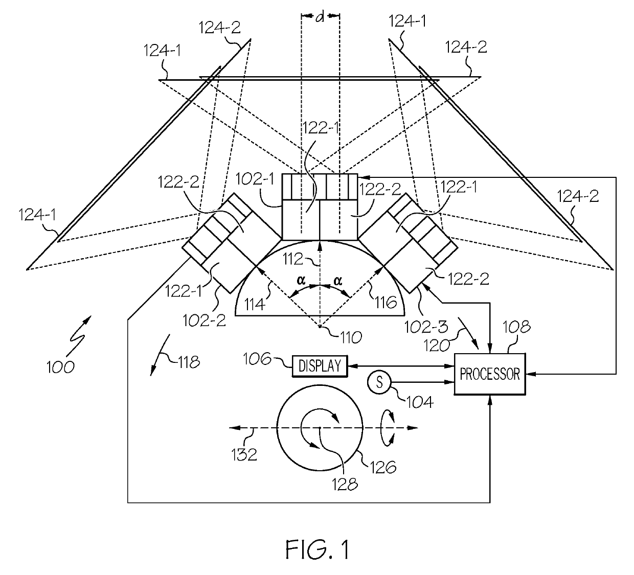
[0018]Referring to FIG. 1, a panoramic image system 100 with parallax mitigation is depicted and includes at least a plurality of image sensors 102 (102-1, 102-2, 102-3 . . . 102-N), a head tra...


PUM


Abstract

A panoramic image system with parallax mitigation includes image sensors, a head tracker, a display, and a processor. Each image sensor is fixedly mounted a predetermined linear distance from a first reference axis and is disposed adjacent to at least one other image sensor and to point in a direction that is offset from its adjacent image sensor by a predetermined angle. The head tracker is configured to sense at least the angular position and movement direction of a viewer's head about a second reference axis and to supply an azimuth position signal representative thereof. The display is configured to selectively display images sensed by each of the image sensors. The processor is in operable communication with the image sensors, head tracker, and display. The processor is configured, based at least on the azimuth position signal, to command the display to display images sensed by only one image sensor.

Description

STATEMENT REGARDING FEDERALLY SPONSORED RESEARCH OR DEVELOPMENT[0001]This invention was made with Government support under Contract No.: D15PC00077 awarded by the Defense Advanced Research Projects Agency (“DARPA”). The Government has certain rights in the invention.TECHNICAL FIELD[0002]The present invention generally relates to panoramic vision systems, and more particularly relates to a panoramic vision system with parallax mitigation.BACKGROUND[0003]Various techniques are known for extending the field of view (FOV) of a camera. One technique is to mount a plurality of cameras on circular or semi-circular mount structure to implement what is sometimes referred to as a camera ring. A camera ring allows for a panoramic view with much less “fish-eye” distortion and higher resolution than a single camera. With a camera ring, the individual cameras each produce images that overlap, and the overlapping images are then stitched together to produce a single, expanded FOV image.[0004]Vario...

Claims


Application Information

Patent Timeline
Patent Type & Authority Applications(United States)
IPC IPC(8): H04N13/128H04N13/371H04N13/239H04N5/232H04N13/38H04N13/332H04N13/398
CPCH04N13/332H04N13/128H04N13/398H04N13/38H04N13/371H04N2213/001H04N5/23238G03B37/04H04N13/282H04N23/698H04N23/90G02B27/017
Inventor LEIPHON, KENHANCOCK, WILLIAM RAY
Owner HONEYWELL INT INC
Why Eureka
Try Eureka