Device comprising a drive system for extending and retracting a conditioned air hose

Pending Publication Date: 2019-10-17
LEBRUN NIMY SA
View PDF0 Cites 1 Cited by
  • Summary
  • Abstract
  • Description
  • Claims
  • Application Information

AI Technical Summary

Benefits of technology

The patent is for a device that can control the length of a hose by rotating its bearings. It also includes a fixed ring that acts as a bearing surface inside the hose. This makes it possible to clamp the hose between the external drive system and the fixed ring, regardless of whether it is reinforced or not. The technical effect of this device is improved control of the hose length, with easier and more secure clamping.

Problems solved by technology

The airliners are often equipped with a small turbine making it possible to generate current and rotating independently of the engines, but such turbines are noisy and energy-intensive, and their use has been prohibited in many airports, above all in Europe.
With the high density of passengers present in the cabin on landing, the heat generated by the lights, the many windows and above all the significant insulation of the fuselage mean that the temperature inside the cabin of an airplane rapidly becomes uncomfortable, even unsupportable.
Although this solution is practical and simple to use, it presents the drawback that the hose has to be unwound from its drum over its entire length each time it is used, even if all the length of the hose is not necessary to connect it to an airplane.
In fact, the head losses (=pressure losses) in a portion of hose wound around the drum are considerable and do not make it possible to blow conditioned air into the cabin of an airplane with a satisfactory pressure.
The hose can simply be packed in the housing, but this simple solution results in severe head losses if the hose is not extended over its entire length before blowing air into the hose.
This generates significant torque losses, generates noise, and is a potential source of failures.
However, it does also present a few drawbacks.
Another drawback of the system described in WO2011064808 is that all the forces for the extension and retraction of the hose are concentrated on the turns whose interface with the outer surface of the hose is therefore greatly stressed and damages rapidly, requiring the changing of the hose at excessively short intervals.
Furthermore, this drive system does not operate on hoses that do not include spirals.
It also makes it possible to prolong the life of a hose, the changing of which is a costly operation.

Method used


Image

  • Device comprising a drive system for extending and retracting a conditioned air hose
  • Device comprising a drive system for extending and retracting a conditioned air hose
  • Device comprising a drive system for extending and retracting a conditioned air hose

Examples


Embodiment Construction

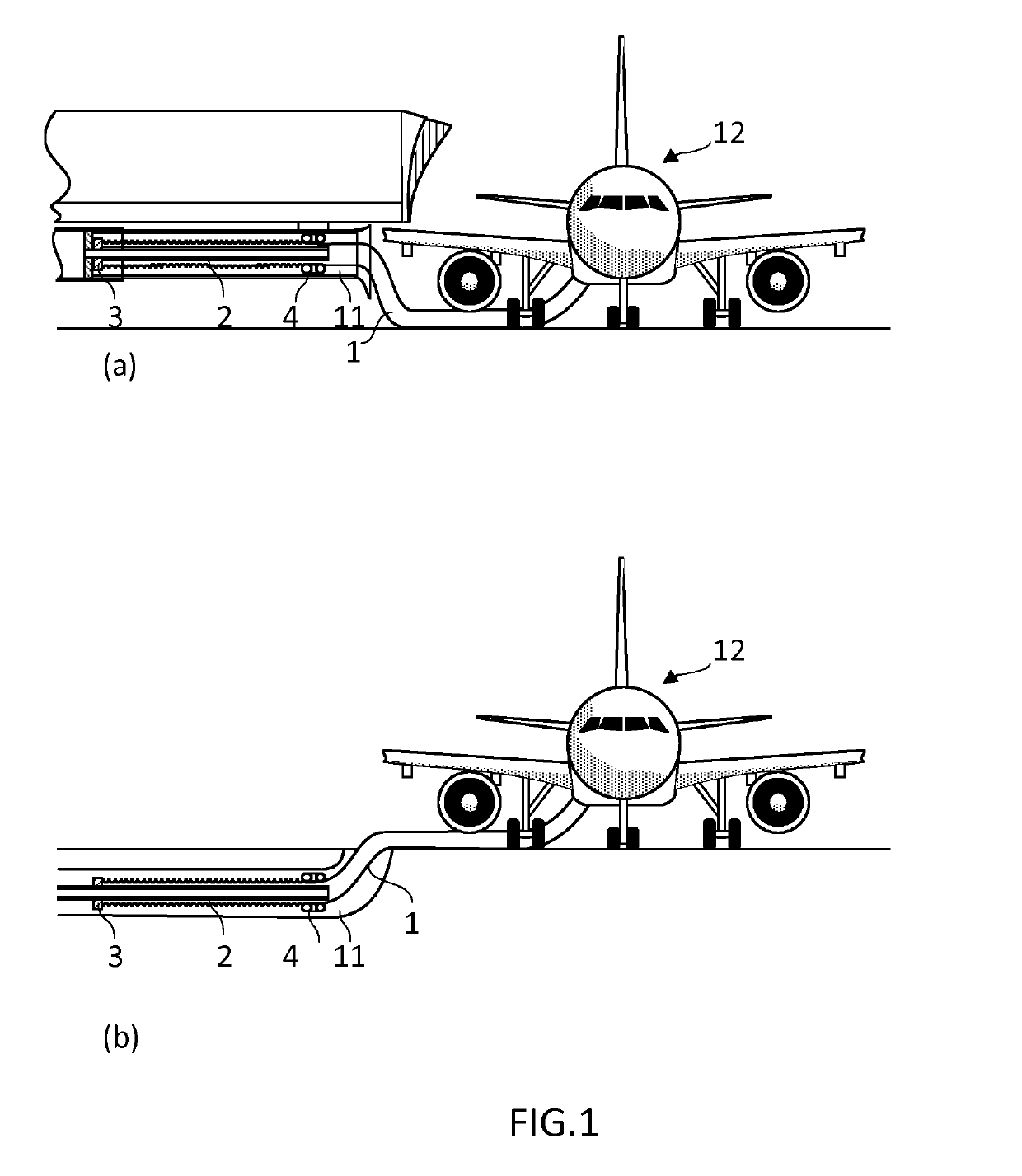
[0035]As represented in FIGS. 1 and 6(c), the device for extending and retracting a hose according to the present invention comprises a tubular housing (11) extending along a longitudinal axis, Z, and comprising a free and open first end. Said tubular housing makes it possible to pack away a hose. The minimum length of the tubular housing must therefore be sufficient to contain a substantial fraction of the length of the hose in its contracted configuration.

[0036]A hose (1) according to the present invention comprises a downstream end which is free and an upstream end which is fluidically connected with a conditioned air unit. The upstream end is away from the first end of the tubular housing and is generally coupled to a rigid tube, either fixedly, or in such a way as to be able to slide along the rigid tube, as explained in more detail below. The downstream end of the hose is generally provided with an element for coupling to a fuselage input of an airplane.

[0037]As illustrated in...


PUM


Abstract

A device for storing and extending a hose for supplying conditioned air to an aircraft on the ground or to any other interior space, includes: a tubular housing (11) extending along a longitudinal axis (Z) and having a free open first end, which tubular housing (11) can store a hose; a hose (1) in fluid communication with a conditioned air unit and having a free downstream end; a drive system (4) that can be used to control the extension and retraction of the hose (1) between a retracted position in which the downstream end of the hose (1) is located in the tubular housing (11), and an extended configuration in which the downstream end of the hose (1) is outside the tubular housing (11) and at a distance from the first end of the tubular housing (11). The drive system (4) has N=4 to 8 drive bearings (6.1-6.6) disposed perpendicularly to the longitudinal axis (Z) and connected to one another by N swivel joints (7.1-7.7), thereby forming a closed chain.

Description

FIELD OF THE INVENTION[0001]The invention relates to an air conditioning system for controlling the temperature of the atmosphere inside an aircraft, such as an airliner, parked on the tarmac of an airport. In particular, the present invention relates to a device for extending and retracting a hose fluidically linking a conditioned air unit to the interior of an aircraft. The device of the present invention comprises a drive system that is reliable, robust, economical and that guarantees a lengthy life of the hose.TECHNOLOGICAL BACKGROUND[0002]For fuel-saving and pollutant emission reduction reasons, the engines of an aircraft, in particular of an airliner, are cut off when it is parked on the ground on the tarmac of an airport. The conditioned air controlling the temperature and humidity of the air in the cabin is therefore also cut off. The airliners are often equipped with a small turbine making it possible to generate current and rotating independently of the engines, but such t...

Claims


Application Information

Patent Timeline
IPC IPC(8): B64F1/36F16H19/06F16L3/01
CPCF16L3/01F16H19/06B64F1/362F16H2019/0613Y02T50/80
Inventor GONSETTE, CHARLES-ETIENNEURBAIN, CLAUDY
Owner LEBRUN NIMY SA
Why Eureka
Try Eureka