Tile with imitation grout line

a technology of imitation grout and tile, which is applied in the field of imitation grout on tiles, can solve the problems of increasing labor and overall cost of the project, wasting time and money, and forming this separation between tiles is often tedious, and achieves the effect of high realistic look, easy formation and easy profil

Inactive Publication Date: 2019-10-17
QUICKSTYLE IND INC
View PDF15 Cites 5 Cited by
  • Summary
  • Abstract
  • Description
  • Claims
  • Application Information

AI Technical Summary

Benefits of technology

[0018]A primary object of the present invention is to provide a tile suitable for use as a flooring surface, which is made from synthetic materials and closely imitates the look of real stone, marble, ceramic or even wood flooring, but which also offers an imitation grout line with a highly realistic look and feel similar to that of an actual grout line.
[0019]Another primary object of the present invention is to provide an inventive tile made from synthetic material(s) that can be readily formed during the manufacturing process to define an exposed portion including a gap substantially or entirely along a selected side thereof and that can be readily profiled to achieve a texture surface thereon which closely matches the look and feel of an actual grout line.
[0020]Yet another primary object of the present invention is to provide a tile with a highly realistic looking and yet imitation grout line that can also be manufactured in variety of colors so as to offer a close match with and consistency of color relative to the overall color of the resulting tile, which has not been achieved before in any existing products.
[0021]An advantage of the tile of the present invention in at least some embodiments is that the material(s) used to make it is / are relatively lightweight and yet sufficiently rigid and durable for a wide variety of applications, and is / are also waterproof.
[0022]A feature of the tile of the present invention is that in at least some embodiments there is an interconnecting mechanism formed along at least one edge thereof or more that facilitates the assembly and installation process.
[0023]Another advantage of the tile of the present invention is that the materials(s) used to make it are capable of assuming a variety of different shapes, colors and / or designs.

Problems solved by technology

Forming this separation between tiles is often tedious and requires the use of spacers to ensure uniformity and alignment of the tiles.
In general, the process of installing tile and creating the grout line involves a significant amount of time, which adds to the labor and overall cost of the project.
While this slight separation may be observable and in some cases may appear as a small seam or even as a micro groove, these types of known tiles do not offer any structure to represent or closely resemble the look and feel of a real grout line.
Furthermore, no such tiles or flooring products are believed to have ever featured a layer of polyvinyl chloride (PVC) combined with a colorant during the manufacturing process so as to provide a variety of colors for the imitation grout line that will match with or closely correspond to the overall color of the resulting tile.
Additionally, of the known flooring products or tiles that exist, none are believed to feature a core layer formed of a densified foam material and having optimal density ranges that is sufficiently rigid and durable for a wide variety of applications.
Also, and even though some of the existing imitation flooring products have correspondingly disposed “tongue” and “groove” structures formed along a side of a tile, there are drawbacks associated with these when it is desired to use such flooring products on a wall surface, as opposed to a floor surface.
More specifically, the installation process for such products on a vertical surface, such as a wall, is cumbersome and further, remains labor intensive and therefore costly.

Method used


Image

  • Tile with imitation grout line
  • Tile with imitation grout line
  • Tile with imitation grout line

Examples


Embodiment Construction

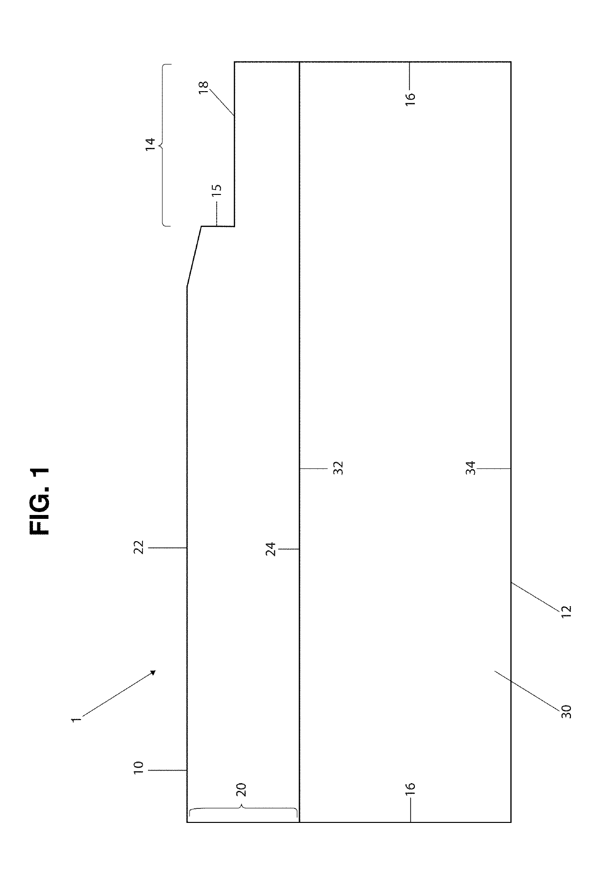
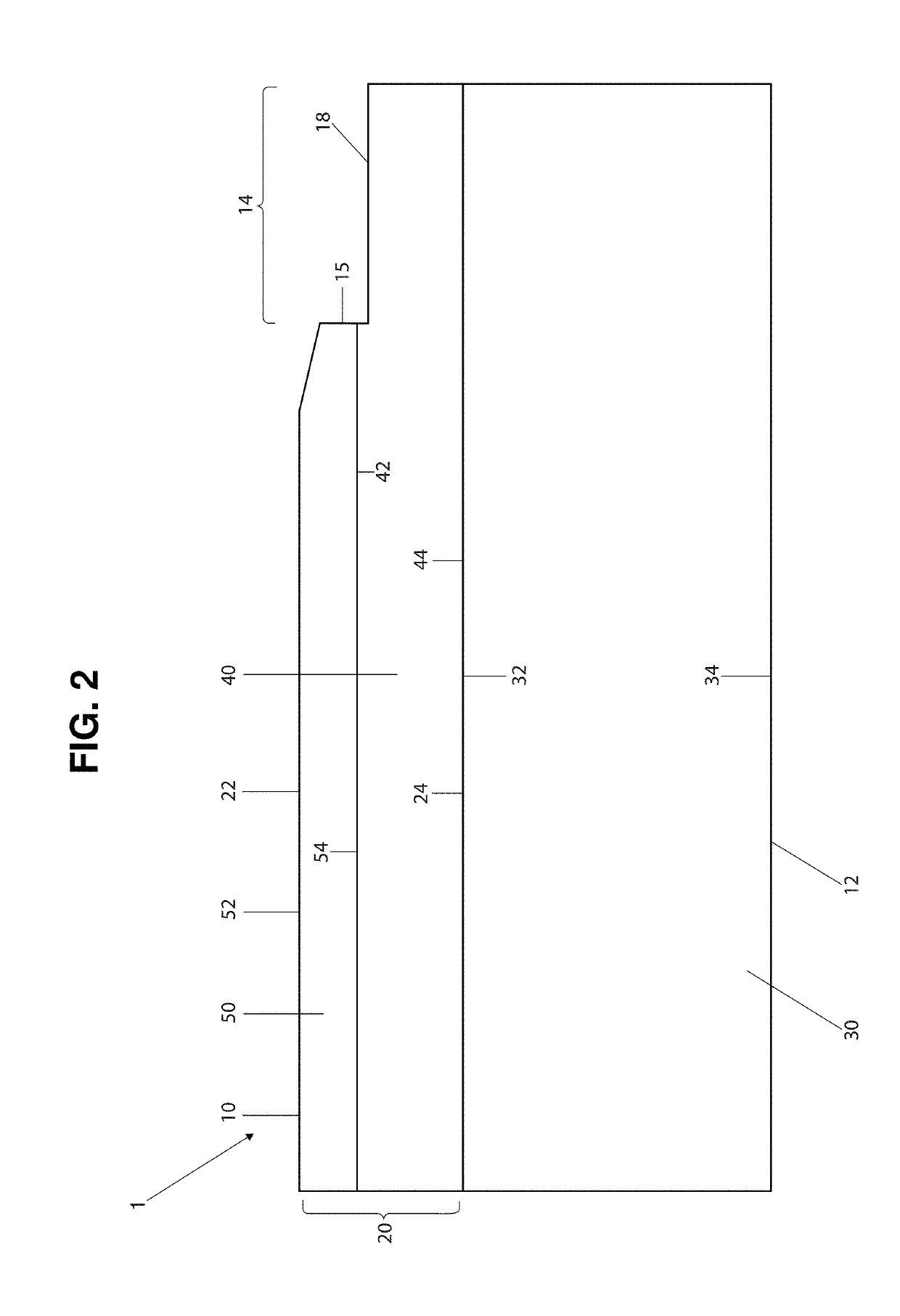
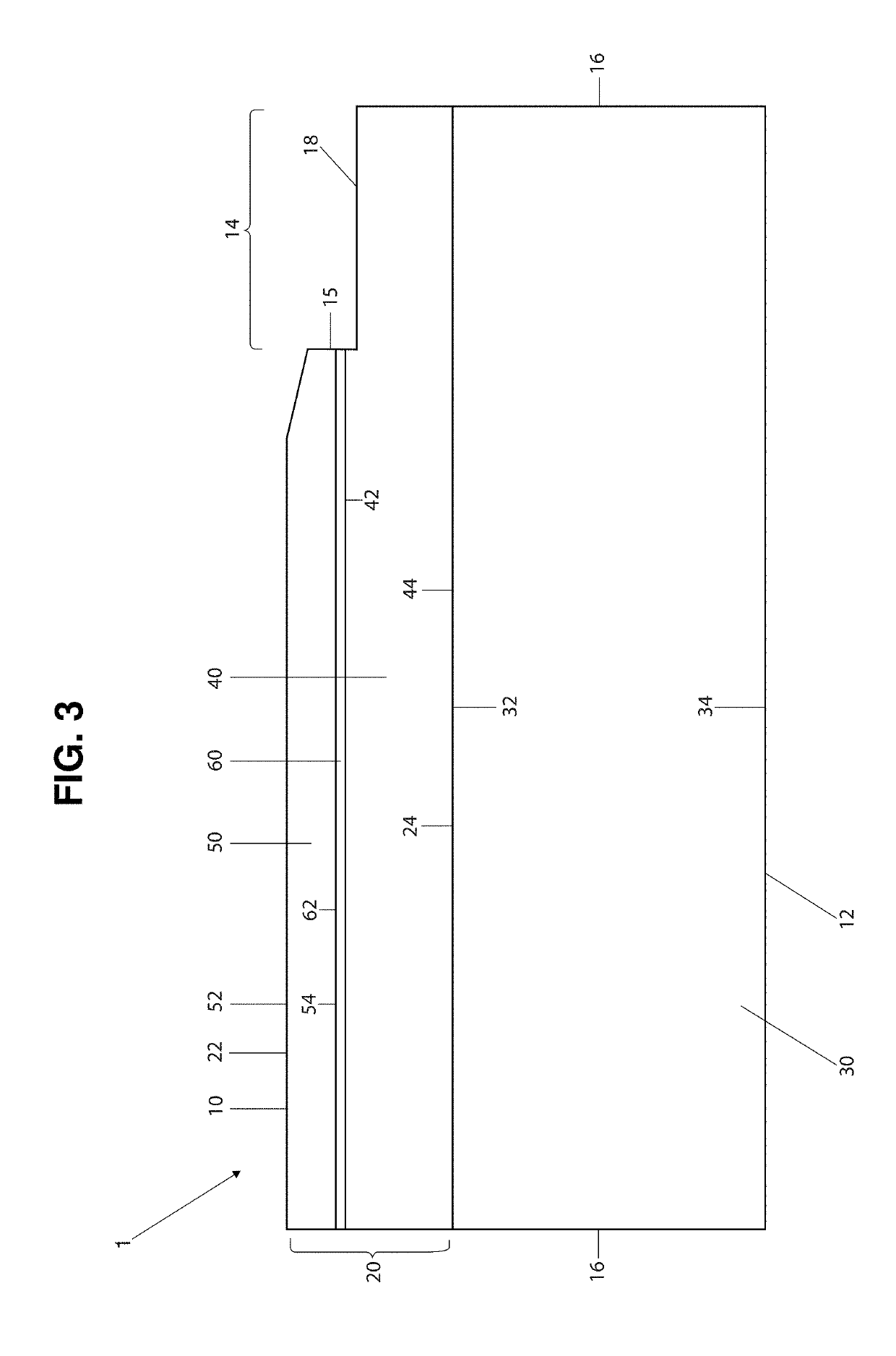
[0073]The present invention is directed towards a tile 1, such as a flooring tile, made from synthetic materials and so as to imitate the look and feel of real stone, marble, ceramic, wood or other materials, but which is further structured to offer a simulated grout line, with a highly realistic look and feel, on or along at least one side or edge of the tile 1. While the tile 1 of the present invention is particularly well suited for use as a flooring tile, it may also readily be used on wall surfaces or in a variety of other applications, and should not be considered as being limited only to flooring applications. As will also be described with regard to at least one embodiment, the tile 1 of the present invention may also be manufactured so as to include a very thin veneer layer of genuine wood or stone.

[0074]In general terms, the tile 1 of the present invention comprises an upper or top section, a lower or core section, and a plurality of sides. For example, and with reference ...


PUM

PropertyMeasurementUnit
densityaaaaaaaaaa
densityaaaaaaaaaa
angleaaaaaaaaaa

Abstract

A tile that may be used as a covering on a floor, wall, or other surface comprises a top section, a protective section, a vinyl layer, an optional core layer, and an exposed portion formed along at least one of its sides and structured to represent an imitation but highly realistic looking grout line. The exposed portion may be formed on at least a portion of the top section. The vinyl layer is generally disposed between the top section and the core layer. The vinyl layer generally comprises a solid vinyl material comprising polyvinyl chloride and stone dust. In some embodiments, the exposed portion is also formed across a middle section of the tile, and may further include an interconnecting mechanism to facilitate installation. The exposed portion may also be formed at least one a portion of the top section above the interconnecting mechanism.

Description

CLAIM OF PRIORITY[0001]This application is a Continuation in Part (CIP) of a currently pending patent application having Ser. No. 16 / 196,974 and a filing date of Nov. 20, 2018, which claims priority to a Continuation in Part (CIP) patent application having Ser. No. 15 / 950,046 and a filing date of Apr. 10, 2018 and which matured into U.S. Pat. No. 10,132,088 on Nov. 20, 2018, which in turn claimed priority to a patent application having Ser. No. 15 / 454,650 and a filing date of Mar. 9, 2017, which matured into U.S. Pat. No. 9,938,726 on Apr. 10, 2018, which in turn claimed priority to a U.S. provisional patent application having Ser. No. 62 / 380,122 and a filing date of Aug. 26, 2016. In addition, the present application claims priority to a currently pending Continuation in Part (CIP) patent application having Ser. No. 15 / 949,979 and a filing date of Apr. 10, 2018, which is set to issue as U.S. Pat. No. 10,233,656 on Mar. 19, 2019, which also claims priority to the above-referenced pa...

Claims


Application Information

Patent Timeline
Patent Type & Authority Applications(United States)
IPC IPC(8): E04F15/02E04F15/10B32B3/06B32B3/26B32B27/20B32B27/30
CPCB32B3/263E04F2201/043E04F15/02038B32B27/304E04F2201/0153E04F15/02033E04F15/107B32B2264/10B32B27/20B32B2307/72B32B3/06E04F2201/023B32B2419/04B32B2307/412B32B3/02B32B5/18B32B5/32B32B7/12B32B9/002B32B9/02B32B9/042B32B9/046B32B21/02B32B21/047B32B21/08B32B21/14B32B27/065B32B27/08B32B27/18B32B27/306B32B2250/02B32B2250/03B32B2250/04B32B2250/05B32B2250/44B32B2255/10B32B2255/102B32B2255/26B32B2264/102B32B2266/0235B32B2307/402B32B2307/4023B32B2307/414B32B2307/538B32B2307/554B32B2307/584B32B2307/732B32B2607/00E04F15/105
Inventor COUREY, STEPHENALFIERE, MICHELE
Owner QUICKSTYLE IND INC
Why Eureka
Try Eureka