RF coil device and RF shield device for different MRI modes
a technology of rf coil and shield, which is applied in the field of rf shields for mr imaging systems, can solve the problems of poor b1 field homogeneity, no coil arrangement is optimal for both reception and transmission modes, and the field is not homogeneous enough to achieve the effect of reducing the quantity of metal, efficient field generation, and efficient us
- Summary
- Abstract
- Description
- Claims
- Application Information
AI Technical Summary
Benefits of technology
Problems solved by technology
Method used
Image
Examples
second embodiment
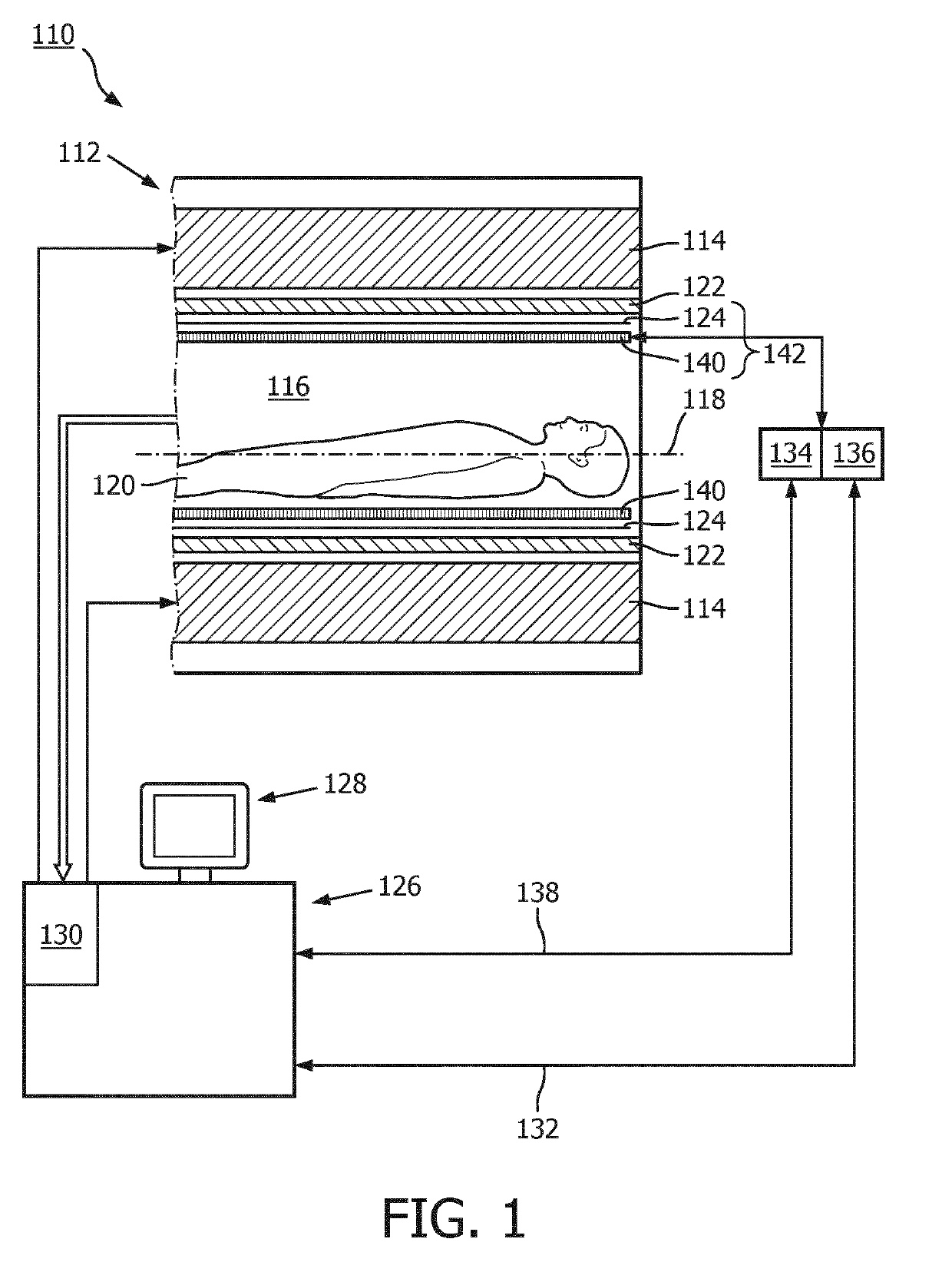
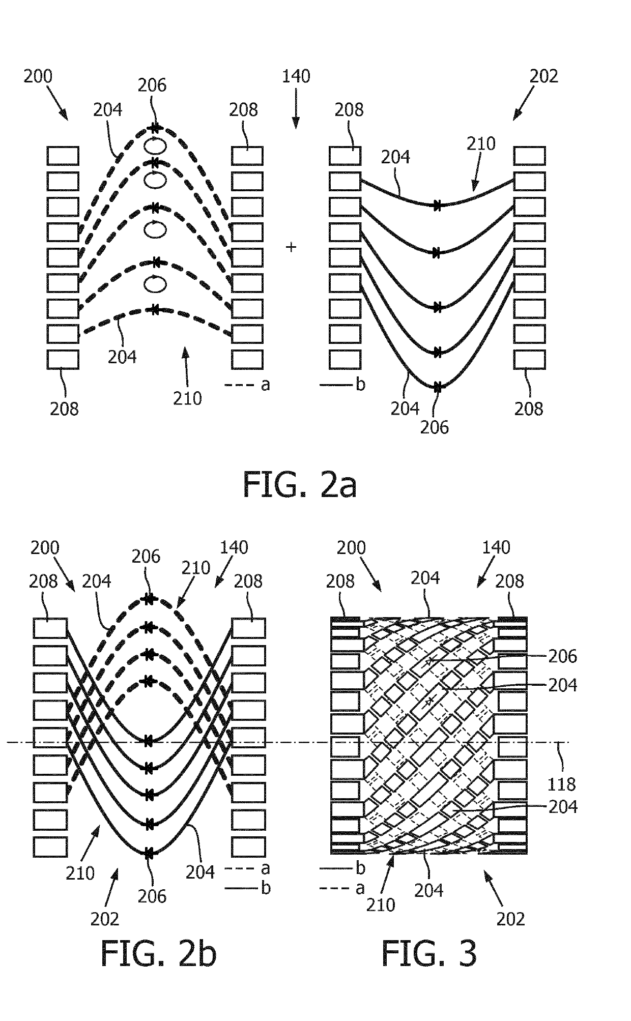
[0068] the first and the second coil 200, 202 are arranged to share the conductive end rings 208. In an alternative embodiment, the first and the second coil 200, 202 are arranged to share only one of the end rings 208. However, in a further alternative embodiment, the first and the second coil 200, 202 each have their individual pair of the end rings 208.
[0069]As can be further seen in FIG. 2, the first coil 200 and the second coil 202 have a coil structure 210 with a parabolic shape of the rungs 204 extending between the end rings 208 of the respective first and second coil 200, 202. The resulting coil structure 210 of the first coil 200 is mirrored compared to a coil structure 210 of the second coil 202. Mirroring is performed in respect to a cylindrical surface at a center axis of the cylindrical surface in an axial direction, i.e. the center axis 118, of the RF coil device 140. With the RF coil device 140 of the present invention, each coil 200, 202 has an optimized coil struct...
third embodiment
[0072]As can be seen in FIG. 3, the RF coil device 140 of the third embodiment comprises a first coil 200 and a second coil 202, which are provided as birdcage coils, and which are concentrically arranged around the center axis 118. The first coil 200 and the second coil 202 have rungs 204, which are provided with a diode 206 provided in a center region thereof. The rungs 204 extend between end rings 208 and are arranged non-parallel to the center axis 118 of the RF coil device 140. In particular, the first coil 200 and the second coil 202 have a coil structure 210 with a spiral shape of the rungs 204 extending between the end rings 208 of the respective first and second coil 200, 202. Hence, the first coil 200 has a coil structure 210 different from a coil structure 210 of the second coil 202.
[0073]The first coil 200 and the second coil 202 are switchable to be active for the different modes of operation, e.g. the first coil 200 for TX mode, and the second coil 202 for RX mode, or ...
seventh embodiment
[0083]In addition to the RF coil devices 140 of the previous embodiments, the RF coil device 140 of the seventh embodiment is provided with a cylindrical coil PCB 222. The coil PCB 222 comprises a dielectric material, which is known as FR-4 in this embodiment.
[0084]The first coil 200 and the second coil 202 are provided as metallization layers 224 at an inner side 226 and an outer side 228 of the coil PCB 222, respectively. The metallization layer 224 refers to a metallic coil structure 210 deposited on the coil PCB 222, which can have essentially any suitable structure.
[0085]In the seventh embodiment, the first coil 200 is active in TX mode, and the second coil 202 is active in RX mode. Therefore, the first coil 200 is provided with a higher thickness compared to a relatively small thickness of the second coil 202. The metallization layers 224 of the first coil 200 and the second coil 202 are formed comprising coil elements 230, which are indicated e.g. in FIG. 7b.The thickness ref...
PUM
 Abstract
Description
Claims
Application Information
 - R&D
- Intellectual Property
- Life Sciences
- Materials
- Tech Scout
- Unparalleled Data Quality
- Higher Quality Content
- 60% Fewer Hallucinations
Browse by: Latest US Patents, China's latest patents, Technical Efficacy Thesaurus, Application Domain, Technology Topic, Popular Technical Reports.
© 2025 PatSnap. All rights reserved.Legal|Privacy policy|Modern Slavery Act Transparency Statement|Sitemap|About US| Contact US: help@patsnap.com


