Airport monitoring system

a technology for monitoring systems and airfields, applied in aircraft traffic control, measurement devices, instruments, etc., can solve problems such as collisions or near-misses, difficult to monitor and visualize ground traffic monitoring, tight schedule ground traffic, etc., to reduce maintenance and recalibration requirements, reduce the radius of curvature, and increase the life of fiber optics

Inactive Publication Date: 2019-10-24
FUGRO TECH
View PDF0 Cites 1 Cited by
  • Summary
  • Abstract
  • Description
  • Claims
  • Application Information

AI Technical Summary

Benefits of technology

[0008]The fiber optic sensors being arranged below the airport territory surface are well protected against external influences and require only a modest amount of cabling. The optic sensor system renders it possible to monitor various relevant conditions. The optic sensor system can for example be used to track traffic movements, monitor intrusion, monitor occupancy of parking lots and the like as is described in more detail with reference to the drawings.
[0009]Preferably, at least one of the fiber optic sensors extends at least substantially according to a straight line in a direction at least substantially parallel to the airport territory surface. A fiber optic sensor is considered to extend substantially according to a straight line if at least its portion embedded in the infrastructure nowhere has a radius of curvature less than 5 m. Preferably the radius of curvature is nowhere less than 20 m. As the at least one fiber optic sensor extends at least substantially according to a straight line optical losses therein are extremely low, and the lifetime of the fiber optic is increased, thereby mitigating maintenance and recalibration requirements. In some embodiments, an external portion of the optic fiber, i.e. extending outside the traffic infrastructure may have a smaller radius of curvature, for example to facilitate connection with other elements. An external portion can be replaced more easily than an internal portion, i.e. embedded in the traffic infrastructure so that a modest risk of failure may be acceptable. A fiber optic sensor may be considered to extend at least substantially parallel to the traffic carrying surface if its distance to a plane defined by the traffic carrying surface does not vary by more than 30%. In other words a depth of a fiber optic sensor may vary between D−0.15*D and D+0.15*D, wherein D is the average value of the depth. Preferably the depth variations are even less than 20% or more preferably less than 10%.

Problems solved by technology

This results in a tightly scheduled ground traffic in the airports involving a wide range of aircraft as well as ground support vehicles.
This results in a complex layout of the airport paths making ground traffic monitoring difficult to monitor and visualize.
Incursions, defined as occurrence of the incorrect presence of an aircraft, vehicle, or person on the protected area of a surface designated for the landing or take-off of aircraft, is one leading source of collisions or near-miss events.
Several deadly accidents involving aircraft collisions have been reported in the past decade, sometimes resulting in explosions of the aircraft with many casualties.
However, the ground radar systems are known to have significant challenges; they are known to be prone to being effected by weather conditions, can result in errors in identifying vehicles both as false positive and false negative especially due to the large variations in size of the vehicles on the ground (from double decker planes to support cars), and are expensive units with short measurement range.
Most importantly however, they need a clear line of sight to make measurements resulting in many “dark spots” with no measurements in the ever expanding airports with complex layouts involving Christmas tree / branching type configuration of buildings and ground ways.

Method used


Image

  • Airport monitoring system
  • Airport monitoring system
  • Airport monitoring system

Examples


Embodiment Construction

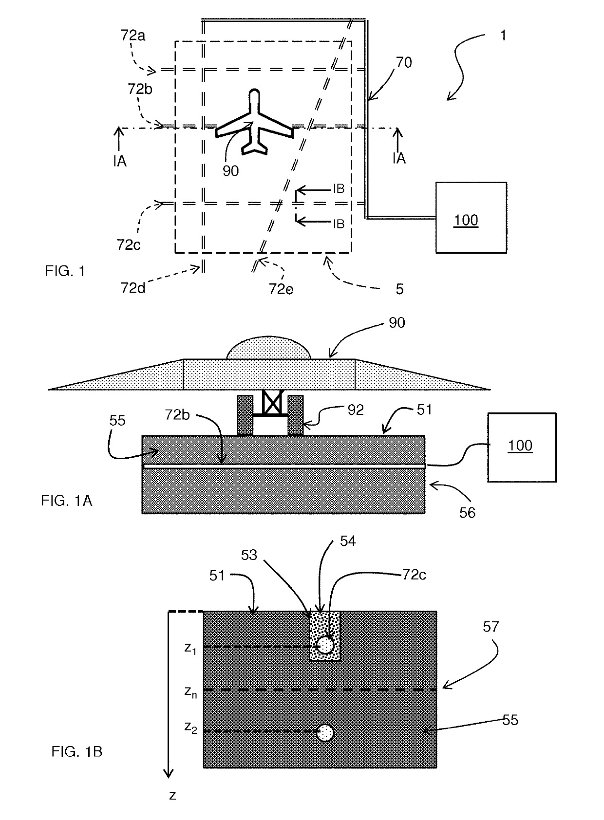
[0028]FIGS. 1, 1A and 1B schematically show an airport monitoring system 1 for monitoring an airport territory 5. Therein FIG. 1A is a cross-section according to IA-IA in FIG. 1 and FIG. 1B is a cross-section according to IB-IB in FIG. 1. The airport monitoring system comprises an airport territory surface 51 as schematically shown in FIG. 1A that has a traffic infrastructure to support conveyance elements 92 of a vehicle 90. Therewith it allows movements of the vehicle 90 over the airport territory surface 51. In the example shown the vehicle 90 is an aircraft and the conveyance elements 92 are the wheels of its landing gear. Other types of vehicles may be service vehicles, such as fueling vehicles, passenger transport vehicles or cargo transport vehicles. Other examples of conveyance elements are caterpillar tracks or runners of a sleigh. In some cases train like vehicles may be used having train wheels as their conveyance elements and being supported by rails in the airport terri...


PUM

PropertyMeasurementUnit
depthaaaaaaaaaa
depthaaaaaaaaaa
depthaaaaaaaaaa

Abstract

The airport monitoring system (1) for monitoring an airport territory (5), comprises an airport territory surface and an optic sensor system (70, 72a, . . . , 72e, 100). The airport territory surface has a traffic infrastructure to support conveyance elements of a vehicle (90), e.g. an aircraft or a service vehicle, therewith allowing movements of the vehicle over the airport territory surface.
The optic sensor system (70, 72a, . . . , 72e, 100), includes an interrogator module (100) and fiber optic sensors (72a, . . . , 72e) coupled thereto. The fiber optic sensors are arranged below the airport territory surface and have a respective plurality of optic strain-sensor elements (722) with mutually different optical characteristics.
The interrogator module (100) transmits optical interrogation signals into the fiber optic sensors and receives respective response optical signals that have been modulated by the fiber optic sensors based on their optical characteristics. The interrogator module (100) identifies changes in the optical characteristics of the received respective response optical signals resulting from strains induced in the optic strain-sensor elements as a result of pressure exerted by a conveyance element (92) of a vehicle (90) on the airport territory surface (51) near a fiber optic sensor.

Description

BACKGROUND[0001]Traffic at the airport runways continues to increase due to a growing demand for air travel. This results in a tightly scheduled ground traffic in the airports involving a wide range of aircraft as well as ground support vehicles. Furthermore, airports are ever expanding such that many crisscrossing grid of runways and taxi lanes are formed over a large area often designed around many terminal buildings. Additionally, the terminal buildings are increasingly being designed to have form factors resembling Christmas tree layouts with multiple branches in between which aircraft is parked or approached for boarding and fueling needs. This results in a complex layout of the airport paths making ground traffic monitoring difficult to monitor and visualize.[0002]In the recent years, while air accident rates have been steadily reducing, ground collisions or near-miss incidents involving aircraft in airports has increased significantly. Incursions, defined as occurrence of the...

Claims


Application Information

Patent Timeline
Patent Type & Authority Applications(United States)
IPC IPC(8): G08G5/06G08G5/00G01L1/24
CPCG08G5/0082G08G5/065G01L1/242
Inventor SINGER, JOHANNES MARIAKARABACAK, DEVREZ MEHMET
Owner FUGRO TECH
Why Eureka
Try Eureka