
Internal combustion engine and hybrid vehicle equipped with it

a hybrid vehicle and internal combustion engine technology, applied in the direction of machines/engines, automatic control of ignition, electric control, etc., can solve the problems of deteriorating emission performance, delay in operation of the injector, and decrease in the voltage applied to the injector, so as to reduce the overlap period, avoid excessive retardation of the energization period, and minimize the overlap period

Active Publication Date: 2019-10-31
TOYOTA JIDOSHA KK
View PDF0 Cites 1 Cited by
  • Summary
  • Abstract
  • Description
  • Claims
  • Application Information

AI Technical Summary

Benefits of technology

The present patent is about reducing the overlap period between the periods when fuel is injected into the combustion chamber of an internal combustion engine and the time when the ignition coil is activated. This is accomplished by controlling the timing of the ignition coil and injector. The goal is to avoid excessive delay in injector activation and minimize the inability of the fuel to atomize, which leads to unburned hydrocarbons in the exhaust gas. The result is an internal combustion engine that reduces emissions and improves efficiency.

Problems solved by technology

Therefore, when the energization period of the injector overlaps with the energization period of the ignition coil, voltage applied to the injector decreases and thereby operation of the injector is delayed.
Delay in the operation of the injector may lead to a shortage of a fuel injection amount and cause deterioration of emission performance due to an air-fuel ratio being made lean.
However, retarding the energization period of the injector will delay the fuel injection timing and shorten the period until ignition in the same cylinder.
Since it takes time for injected fuel to be atomized, if the energization period of the injector is excessively retarded, unburned HC is generated because enough time for fuel atomization cannot be obtained, and HC concentration in exhaust gas increases.
In the correction processing under such the setting processing, the controller may advance the energization period of the ignition coil within a range where the ignition timing isn't advanced excessively over a knocking ignition timing, or may retard the energization period of the ignition coil within a range where the ignition timing isn't retarded excessively over a misfire limit ignition timing.
In the correction processing under such the setting processing, when the overlap period is not removed by correcting the energization period of the injector within a range from a predetermined retardation limit to a predetermined advance limit, the controller may advance the energization period of the ignition coil within a range where the ignition timing isn't advanced excessively over the knocking ignition timing, or may retard the energization period of the ignition coil within a range where the ignition timing isn't retarded excessively over the misfire limit ignition timing.

Method used


Image

  • Internal combustion engine and hybrid vehicle equipped with it
  • Internal combustion engine and hybrid vehicle equipped with it
  • Internal combustion engine and hybrid vehicle equipped with it

Examples


first embodiment

6. Engine Control

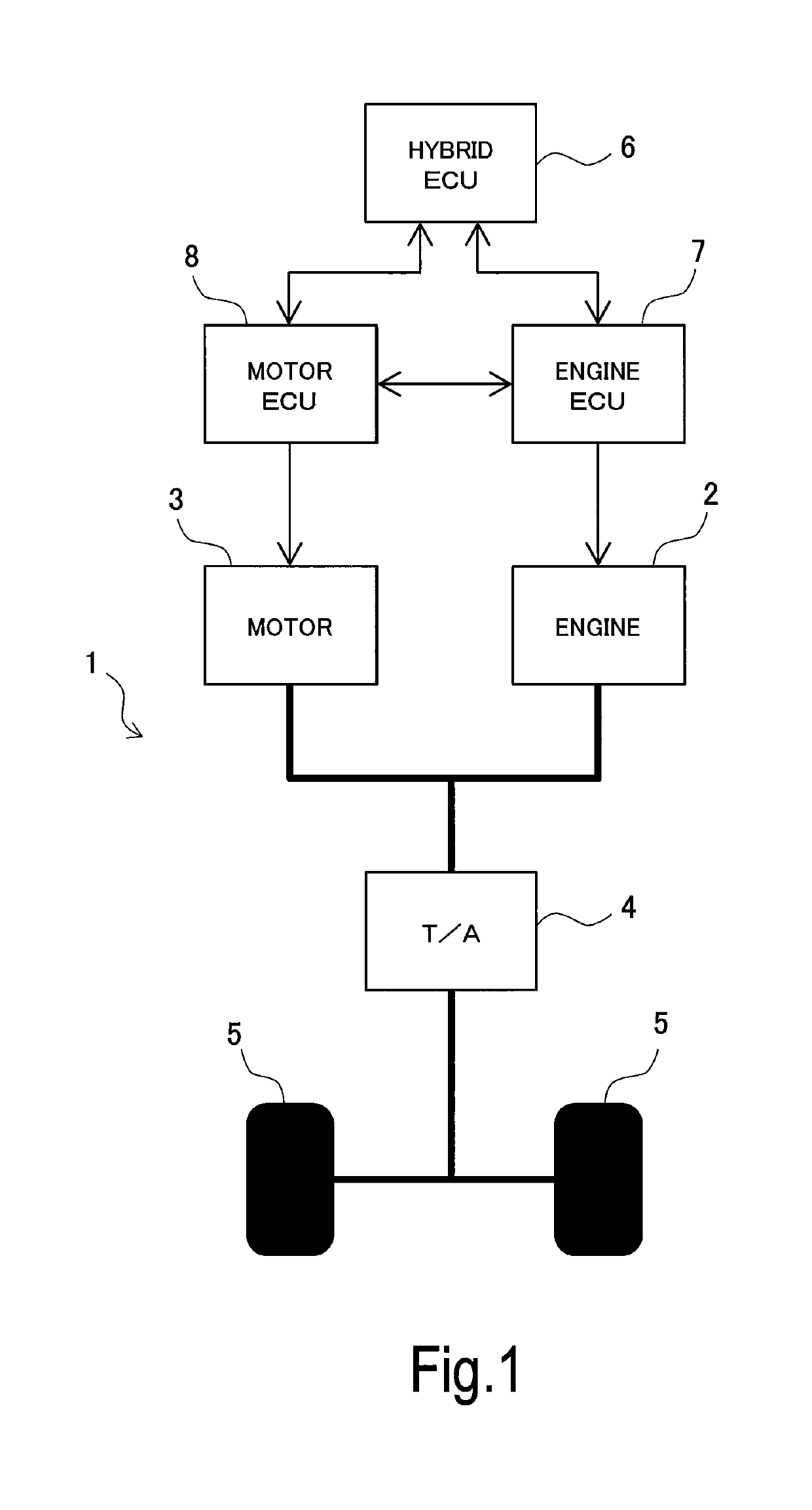
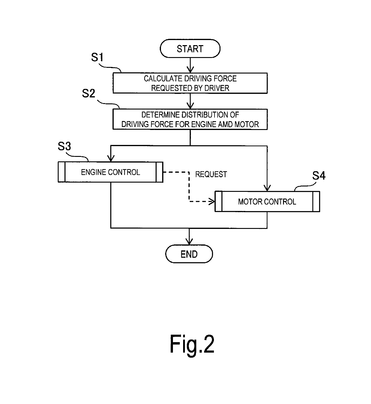
[0057]Hereinafter, with respect to the engine control executed by the engine ECU 7, three embodiments will be described. Note that the engine control described below is engine control constituting driving force control of the hybrid vehicle 1 and is included in the engine control executed in step S3 of the control flow shown in FIG. 2.

[0058]FIG. 8 is a flowchart showing a control flow of the engine control according to the first embodiment. The engine ECU 7 executes a routine expressed by this control flow at a predetermined cycle. First, the engine ECU 7 executes setting processing consisting of processing in strep S101 and processing in step S102.

[0059]In step S101, the engine ECU 7 sets an energization period of the ignition coil 27 in accordance with an operating condition of the engine 2. More specifically, the engine ECU 7 calculates a MBT and a knocking ignition timing based on the operating condition of the engine 2, and selects the ignition timing on a reta...

second embodiment

7. Engine Control

[0078]FIG. 9 is a flowchart showing a control flow of the engine control according to the second embodiment. In the second embodiment, the engine ECU 7 executes a routine expressed by this control flow at a predetermined cycle. In the control flow shown in FIG. 9, the processing given the same step number as the processing in the control flow shown in FIG. 8 means the processing having the same content as the processing in the control flow shown in FIG. 8. Concerning such the processing, description about the content thereof is omitted or simplified.

[0079]In the second embodiment, first, the engine ECU 7 executes setting processing consisting of processing in strep S101, processing in step S105 and processing in step S121. In step S101, the engine ECU 7 sets an energization period of the ignition coil 27 in accordance with an operating condition of the engine 2. In step S105, the engine ECU 7 calculates an advance limit and a retardation limit of an energization per...

third embodiment

8. Engine Control

[0087]FIG. 10 is a flowchart showing a control flow of the engine control according to the third embodiment. In the third embodiment, the engine ECU 7 executes a routine expressed by this control flow at a predetermined cycle. In the control flow shown in FIG. 10, the processing given the same step number as the processing in the control flow shown in FIG. 8 means the processing having the same content as the processing in the control flow shown in FIG. 8. Concerning such the processing, description about the content thereof is omitted or simplified.

[0088]In the third embodiment, first, the engine ECU 7 executes setting processing consisting of processing in strep S102, processing in step S131 and processing in step S132. In step S102, the engine ECU 7 sets an energization period of the injector 25 in accordance with an operating condition of the engine 2.

[0089]In step S131, the engine ECU 7 calculates an advance limit of the energization period of the ignition coil...


PUM


Abstract

An internal combustion engine according to the present disclosure has an ignition coil and an injector that share a power source, and has a controller that controls energization to the ignition coil and energization to the injector. The controller executes setting processing and correction processing. In the setting processing, the controller sets an energization period of the ignition coil in accordance with an operating condition of the internal combustion engine. In the correction processing, when the energization period of the ignition coil overlaps with an energization period of the injector, the controller corrects the energization period of the ignition coil so as to reduce an overlap period between the energization period of the ignition coil and the energization period of the injector.

Description

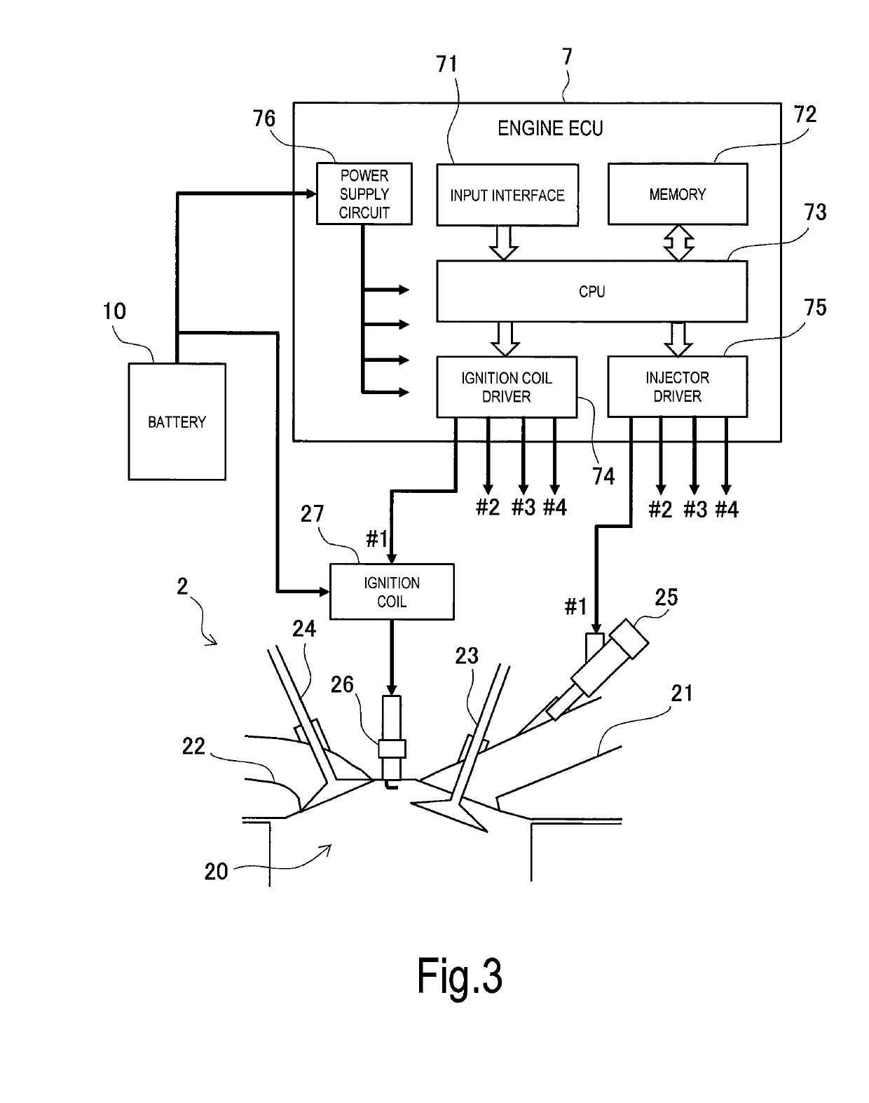
CROSS-REFERENCE TO RELATED APPLICATION[0001]This application claims priority to Japanese Patent Application No. 2018-084375, filed on Apr. 25, 2018, which is incorporated by reference herein in its entirety.BACKGROUNDField[0002]The present disclosure relates to an internal combustion engine, especially a spark ignition type internal combustion engine and a hybrid vehicle equipped with the internal combustion engine.Background Art[0003]As for a spark ignition type internal combustion engine, particularly a multi-cylinder internal combustion engine, there is a case where an energization period of an injector partially overlaps with an energization period of an ignition coil. In general, the ignition coil and the injector share a power source. Therefore, when the energization period of the injector overlaps with the energization period of the ignition coil, voltage applied to the injector decreases and thereby operation of the injector is delayed. Delay in the operation of the injector...

Claims


Application Information

Patent Timeline
Patent Type & Authority Applications(United States)
IPC IPC(8): F02P5/04F02P5/15F02D41/34B60W20/00
CPCF02D41/345B60W20/00F02P5/15B60K6/24B60Y2200/92F02P5/045F02D41/34F02P5/145F02D37/02B60W10/06F02P5/1502F02P15/006F02D41/20F02D2041/2082F02P3/045F02P5/152B60W20/10B60W10/08Y02T10/40Y02T10/62
Inventor OTA, TOMOYA
Owner TOYOTA JIDOSHA KK
Learn More