Double-row self-aligning roller bearing and protrusion prevention jig
a self-aligning, roller bearing technology, applied in the direction of roller bearings, rigid supports of bearing units, mechanical apparatus, etc., can solve the problems of lack of stability, time-consuming work, etc., to improve the wear resistance of each roller, reduce the risk of rolling damage, and improve the fittability of the roller
- Summary
- Abstract
- Description
- Claims
- Application Information
AI Technical Summary
Benefits of technology
Problems solved by technology
Method used
Image
Examples
first embodiment
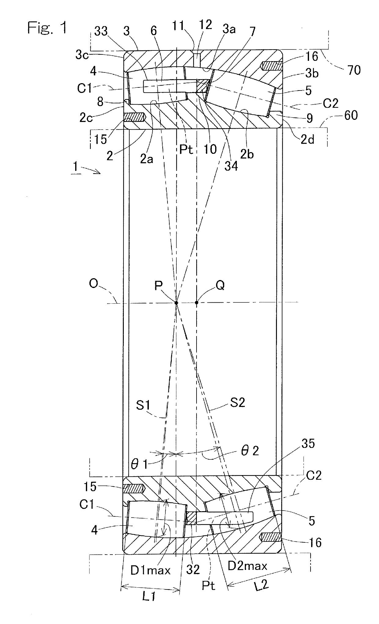
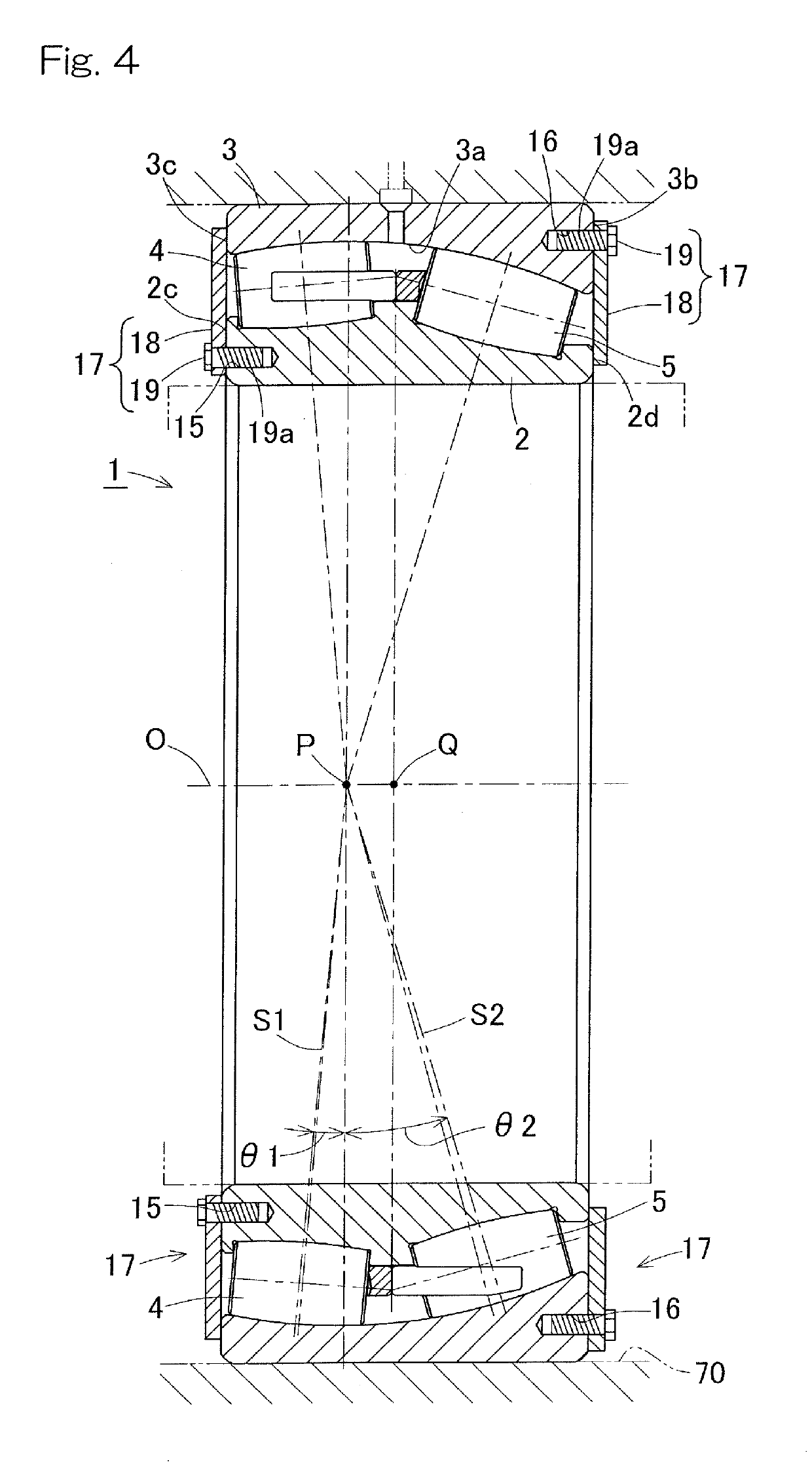
[0061]FIG. 1 is a cross-sectional view of a double-row self-aligning roller bearing according to the present invention. In the double-row self-aligning roller bearing 1, rollers 4 and 5 in two rows, that is, left and right two rows juxtaposed to each other in a bearing width direction are interposed between an inner ring 2 mounted to a shaft 60 and an outer ring 3 mounted to a housing 70. The outer ring 3 has a spherical raceway surface 3a, and the rollers 4 and 5 in the left and right rows each have an outer circumferential surface having a cross-sectional shape that matches the raceway surface 3a of the outer ring 3. In other words, the outer circumferential surfaces of the rollers 4 and 5 are rotation curved surfaces obtained by rotating, about center lines C1 and C2, a circular arc extending along the raceway surface 3a of the outer ring 3. On the inner ring 2, raceway surfaces 2a and 2b in double rows having cross-sectional shapes along the outer circumferential surfaces of the...
second embodiment
[0080]A double-row self-aligning roller bearing will be described with reference to FIG. 6.
[0081]The double-row self-aligning roller bearing 1 includes a retainer 7A with an inclination angle. The retainer 7A for the right row shown in FIG. 6 is a retainer for retaining the rollers 5 in the row that receives an axial load. The retainer 7A has an inclination angle β at which a radially outer surface 35Aa of each pillar portion 35A is inclined radially inward from a proximal end side toward a distal end side. The inclination angle β is an angle relative to the bearing central axis O. The inclination angle β of the retainer 7A is set within a range of greater than zero and not greater than a maximum diameter angle α2 of the rollers 5 (02). The maximum diameter angle α2 is an inclination angle, relative to a plane perpendicular to the bearing central axis O, at the position at which the maximum diameter D2max of the rollers 5 in the right row is obtained.
[0082]The radially inner surfac...
third embodiment
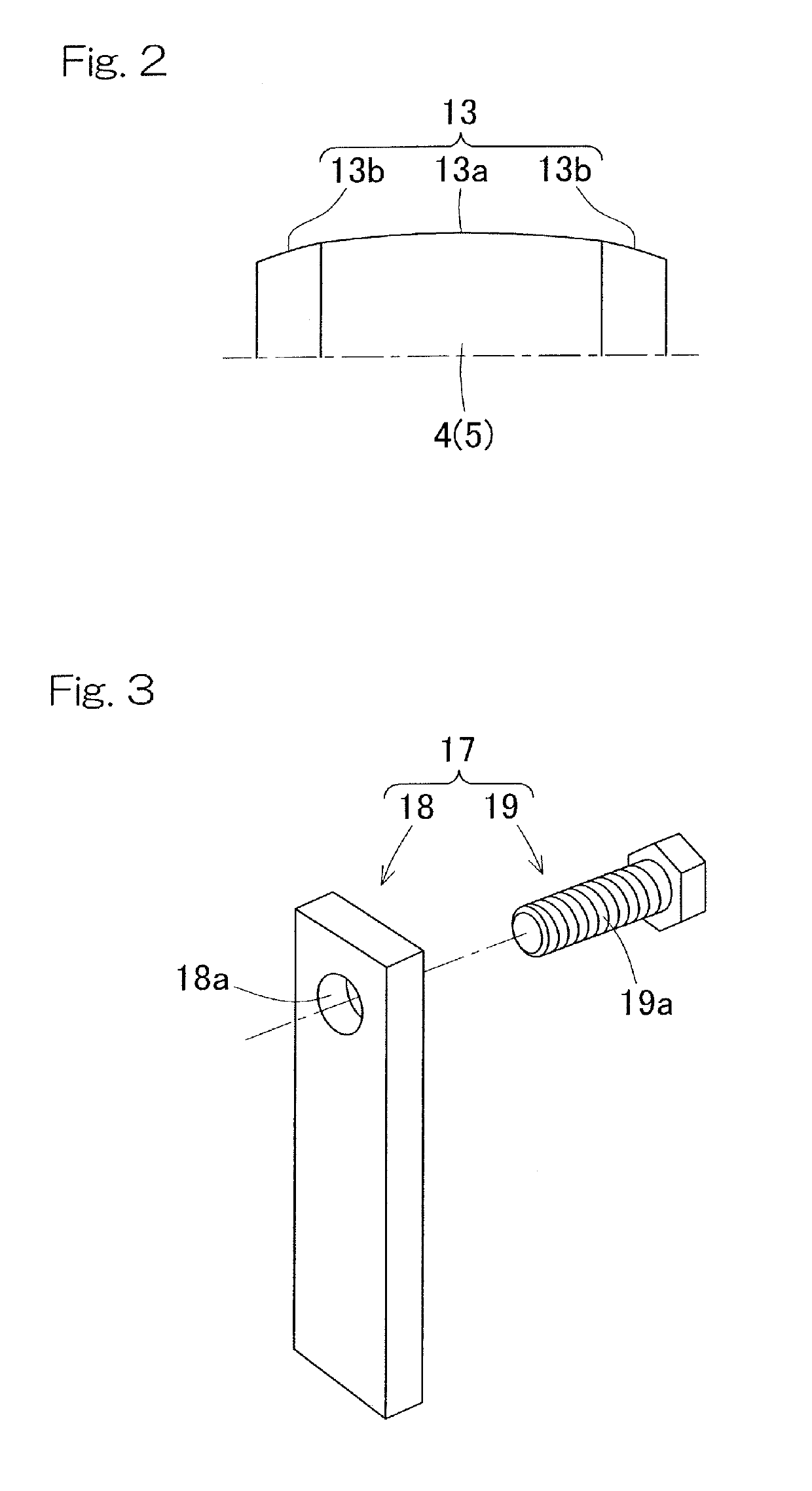
[0084]In a double-row self-aligning roller bearing as shown in FIG. 7, the rollers 4 and 5 in the respective left and right rows may each have crownings Cw at the end portions 13b and 13c of the roller rolling surface 13 thereof. As each crowning Cw in this example, a complex R crowning that increases a drop amount by making the end portion 13b or 13c of the roller rolling surface 13 smaller than a reference R of the roller rolling surface 13 is used. A length Ls of a roller center portion 13a at which no crowning Cw is provided (hereinafter, referred to as “straight length”) may be 50% to 70% and preferably 60% of a roller overall length L1 (L2).
[0085]FIG. 8 is a diagram showing a relationship between a straight length and a PV value (surface pressure x sliding velocity) when an average wind load is applied to a double-row self-aligning roller bearing for supporting a windmill main shaft. FIG. 9 is a diagram showing a relationship between the straight length and bearing life. From...
PUM
 Abstract
Description
Claims
Application Information
 - R&D
- Intellectual Property
- Life Sciences
- Materials
- Tech Scout
- Unparalleled Data Quality
- Higher Quality Content
- 60% Fewer Hallucinations
Browse by: Latest US Patents, China's latest patents, Technical Efficacy Thesaurus, Application Domain, Technology Topic, Popular Technical Reports.
© 2025 PatSnap. All rights reserved.Legal|Privacy policy|Modern Slavery Act Transparency Statement|Sitemap|About US| Contact US: help@patsnap.com


