
Protection circuit applied to electronic device and associated protection method

a protection circuit and electronic device technology, applied in the field of electronic devices, can solve problems such as power supply limitation of a common electronic device, and power consumption of an electronic device that is too large, and achieve the effect of preventing system abnormality or damag

Active Publication Date: 2019-11-07
MEDIATEK INC
View PDF0 Cites 0 Cited by
  • Summary
  • Abstract
  • Description
  • Claims
  • Application Information

AI Technical Summary

Benefits of technology

The patent aims to provide a protection circuit that can quickly shut down one of multiple power outputs in case of overly large power consumption to prevent system abnormality or damage.

Problems solved by technology

However, the power supply of a common electronic device is limited.
Thus, if an electronic device concurrently charges two or more mobile devices and one of the mobile devices uses a power supply specification having a high power output, the power consumption of the electronic device can be overly large, causing system abnormality or damage.

Method used


Image

  • Protection circuit applied to electronic device and associated protection method
  • Protection circuit applied to electronic device and associated protection method
  • Protection circuit applied to electronic device and associated protection method

Examples


Embodiment Construction

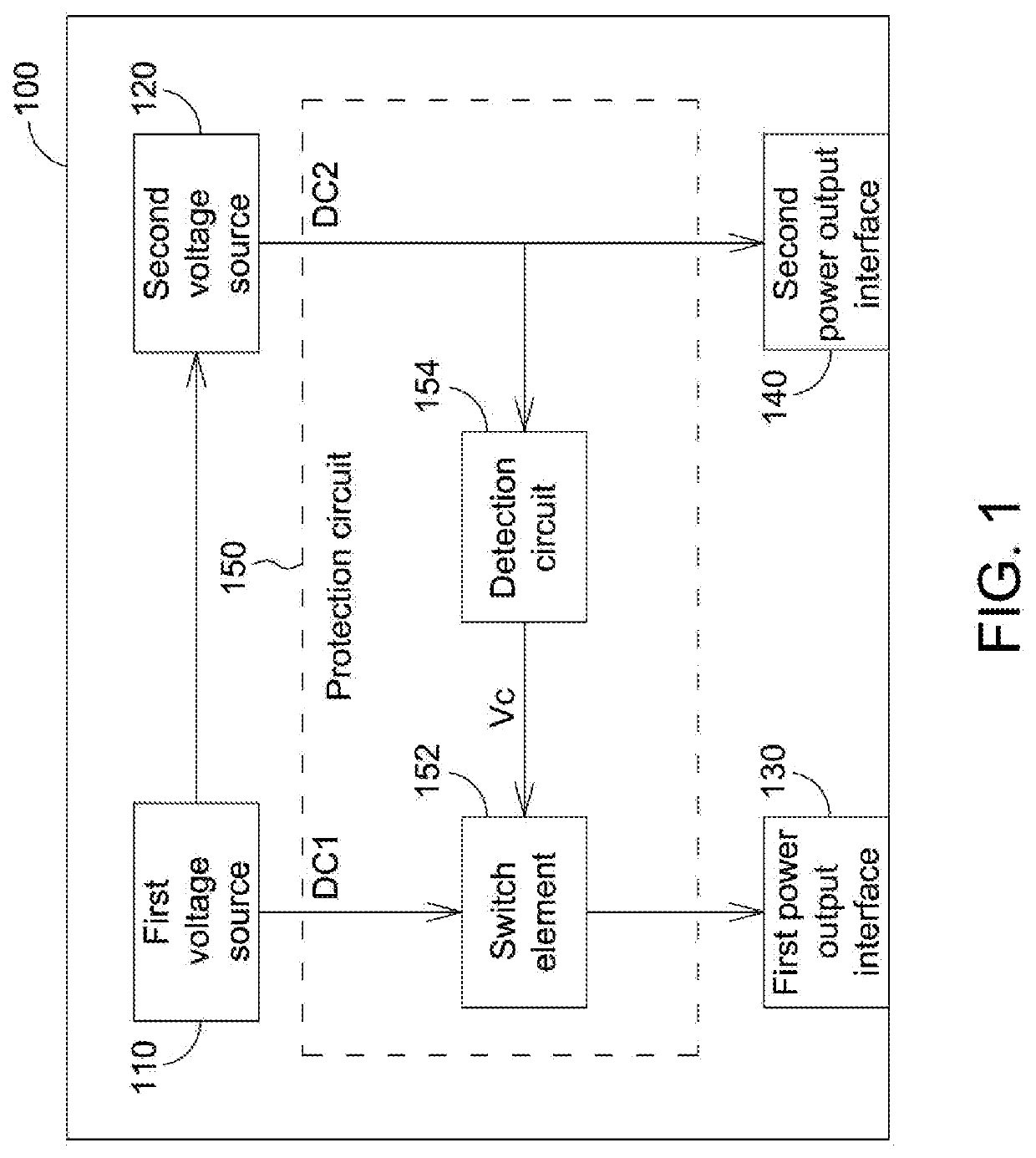
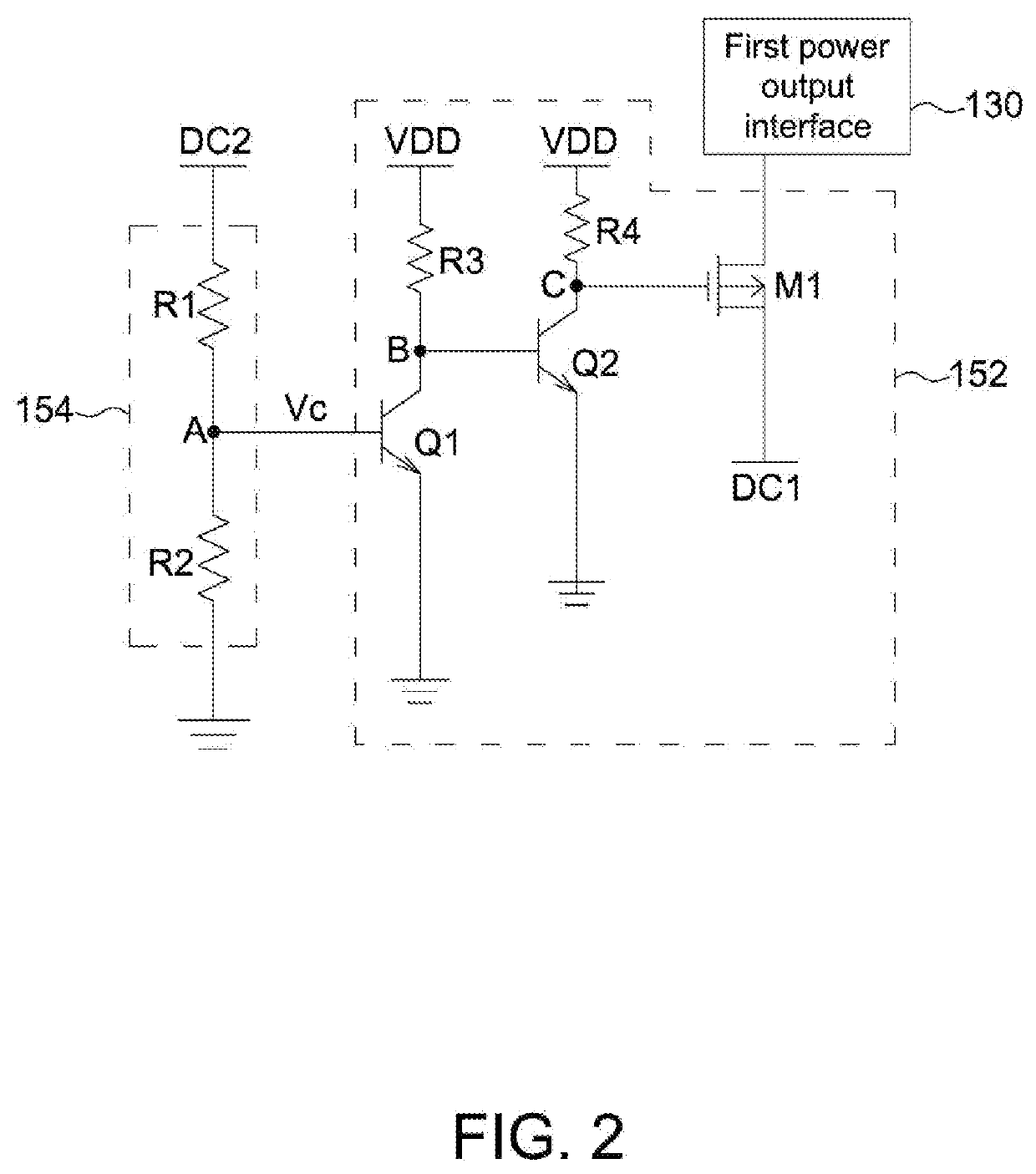
[0012]FIG. 1 shows a block diagram of an electronic device 100 according to an embodiment of the present invention. As shown in FIG. 1, the electronic device 100 includes a first voltage source 110, a second voltage source 120, a first power output interface 130, a second power output interface 140, and a protection circuit 150. The protection circuit 150 includes a switch element 152 and a detection circuit 154. In this embodiment, the electronic device 100 may be a display device or any other electronic device capable of charging another device, the first power output interface 130 is a data transmission connector capable of outputting a fixed power / voltage value, and the second power output interface 140 has multiple power supply specifications with different output power / voltage values. For example, the second power output interface 140 supports the Universal Serial Bus (USB) type-C specifications.

[0013]In the embodiment in FIG. 1, the first voltage source 110 generates a first ...


PUM


Abstract

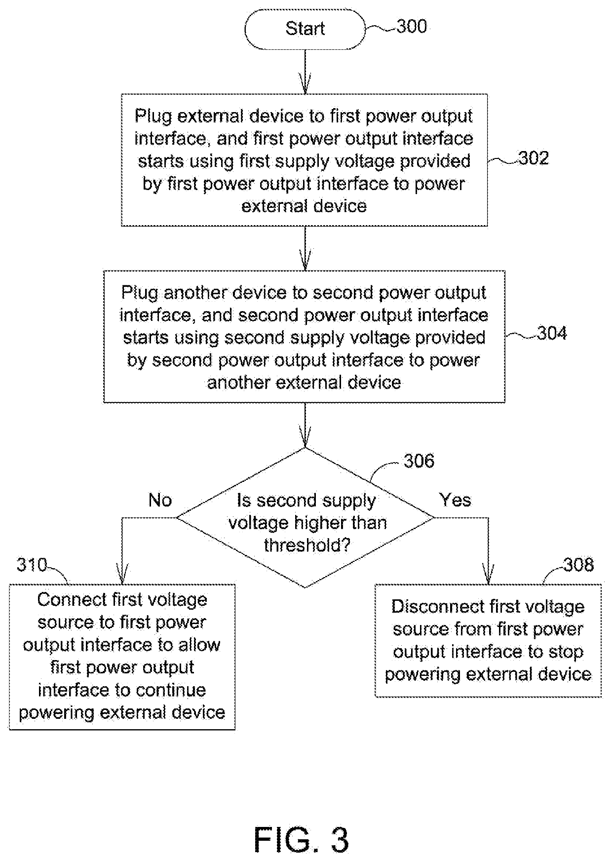
A protection circuit for an electronic device including a first power output interface and a second power output interface is disclosed. The protection circuit includes a first switch element and a detection circuit. The first switch element is coupled between a first voltage source and the first power output interface. In an operation of the protection circuit, the detection circuit detects an output voltage value of the second power output interface to generate a detection result, and the first switch element, according to the detection result, connects the first voltage source to the first power output interface to allow the first power output interface to output power to an external terminal, or disconnects the first voltage source from the first power output interface.

Description

[0001]This application claims the benefit of Taiwan application Serial No. 107114870, filed May 2, 2018, the subject matter of which is incorporated herein by reference.BACKGROUND OF THE INVENTIONField of the Invention[0002]The invention relates to an electronic device having multiple power output interfaces.Description of the Related Art[0003]In Universal Serial Bus (USB) type-C compliant specifications, many power supply specifications having different output powers are defined to allow an electronic device to have a higher power output efficiency. However, the power supply of a common electronic device is limited. Thus, if an electronic device concurrently charges two or more mobile devices and one of the mobile devices uses a power supply specification having a high power output, the power consumption of the electronic device can be overly large, causing system abnormality or damage.SUMMARY OF THE INVENTION[0004]Therefore, it is an object of the present invention to provide a pr...

Claims


Application Information

Patent Timeline
Patent Type & Authority Applications(United States)
IPC IPC(8): H02H3/04G06F1/28H02H3/20
CPCH02H3/20H02H3/048G06F1/28G06F1/263G06F1/305
Inventor CHUANG, TSUI-CHUANLIU, MING-RUEICHIANG, DIEN-SHENKAO, CHIEN-TAI
Owner MEDIATEK INC
Learn More