
Antenna array codebook with beamforming coefficients adapted to an arbitrary antenna response of the antenna array

a beamforming coefficient and antenna array technology, applied in the field of multi-antenna techniques, can solve the problems of antenna array-dependent codebook designs that are not desired, specific codebooks that are not suited to controlling another or arbitrary antenna arrays,

Active Publication Date: 2019-11-14
FRAUNHOFER GESELLSCHAFT ZUR FOERDERUNG DER ANGEWANDTEN FORSCHUNG EV
View PDF0 Cites 34 Cited by
  • Summary
  • Abstract
  • Description
  • Claims
  • Application Information

AI Technical Summary

Benefits of technology

The patent describes a method for transmitting information about the actual antenna array used at a base station to a user equipment (UE) without transmitting a large amount of data. The method involves using characteristic matrices based on a model of the antenna array or a measurement of the array to describe its radiation characteristics. These matrices are used to adapt a codebook, which is then transmitted to the UE. The UE then generates the needed codebook based on the received parameters and the characteristic matrices and selects the best codebook vectors or beamforming weights for feedback to the base station. This reduces the control information overhead and improves the accuracy of the channel estimation and beam refining processes.

Problems solved by technology

While a 2D DFT based codebook may be used as a codebook for uniform rectangular antenna arrays (URAs), since the antenna responses of the URA may be represented by an oversampled DFT basis vectors, a 2D-DFT based codebook may not be used for an arbitrary shaped antenna array as this may result in undesired directional beam patterns.
In other words, while a specific codebook for one antenna array may be used for controlling a specific antenna array (different from the one antenna array), this specific codebook may not be suited for controlling another or arbitrary antenna array.
However, such antenna array-dependent codebook designs are not desired as the codebooks are also dependent on the antenna configuration, such as the number of antenna ports, or an orientation of the antennas in the antenna array.

Method used


Image

  • Antenna array codebook with beamforming coefficients adapted to an arbitrary antenna response of the antenna array
  • Antenna array codebook with beamforming coefficients adapted to an arbitrary antenna response of the antenna array
  • Antenna array codebook with beamforming coefficients adapted to an arbitrary antenna response of the antenna array

Examples


Embodiment Construction

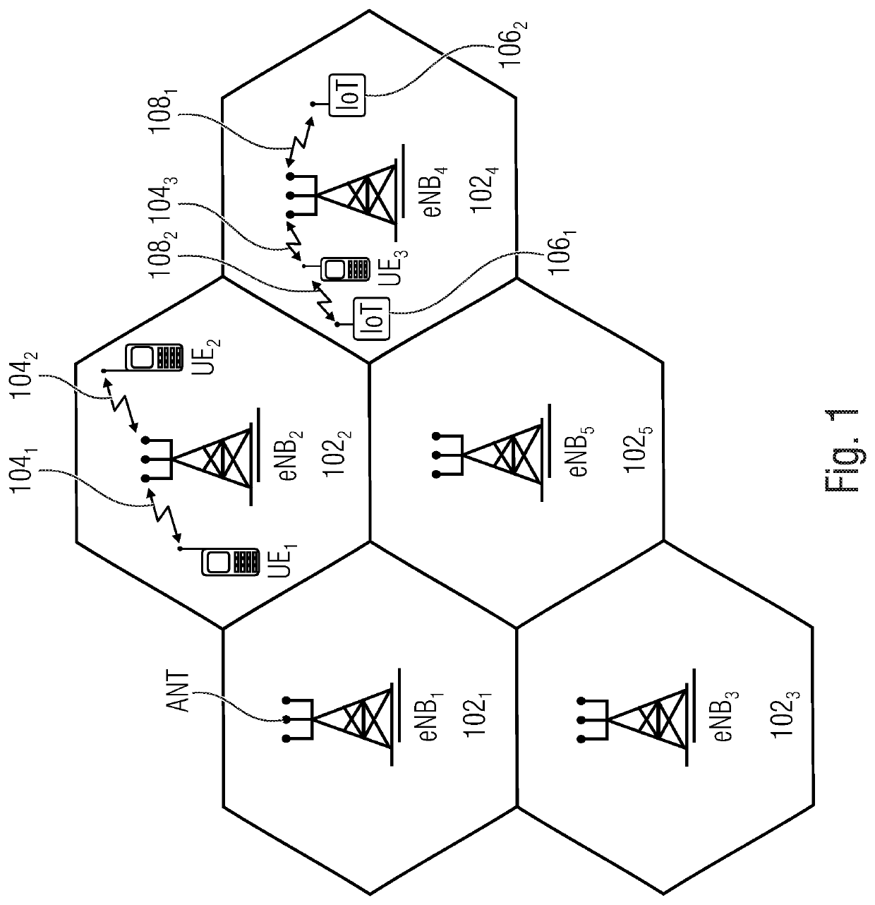
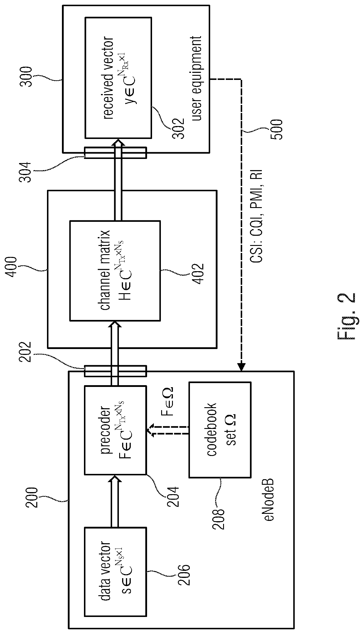
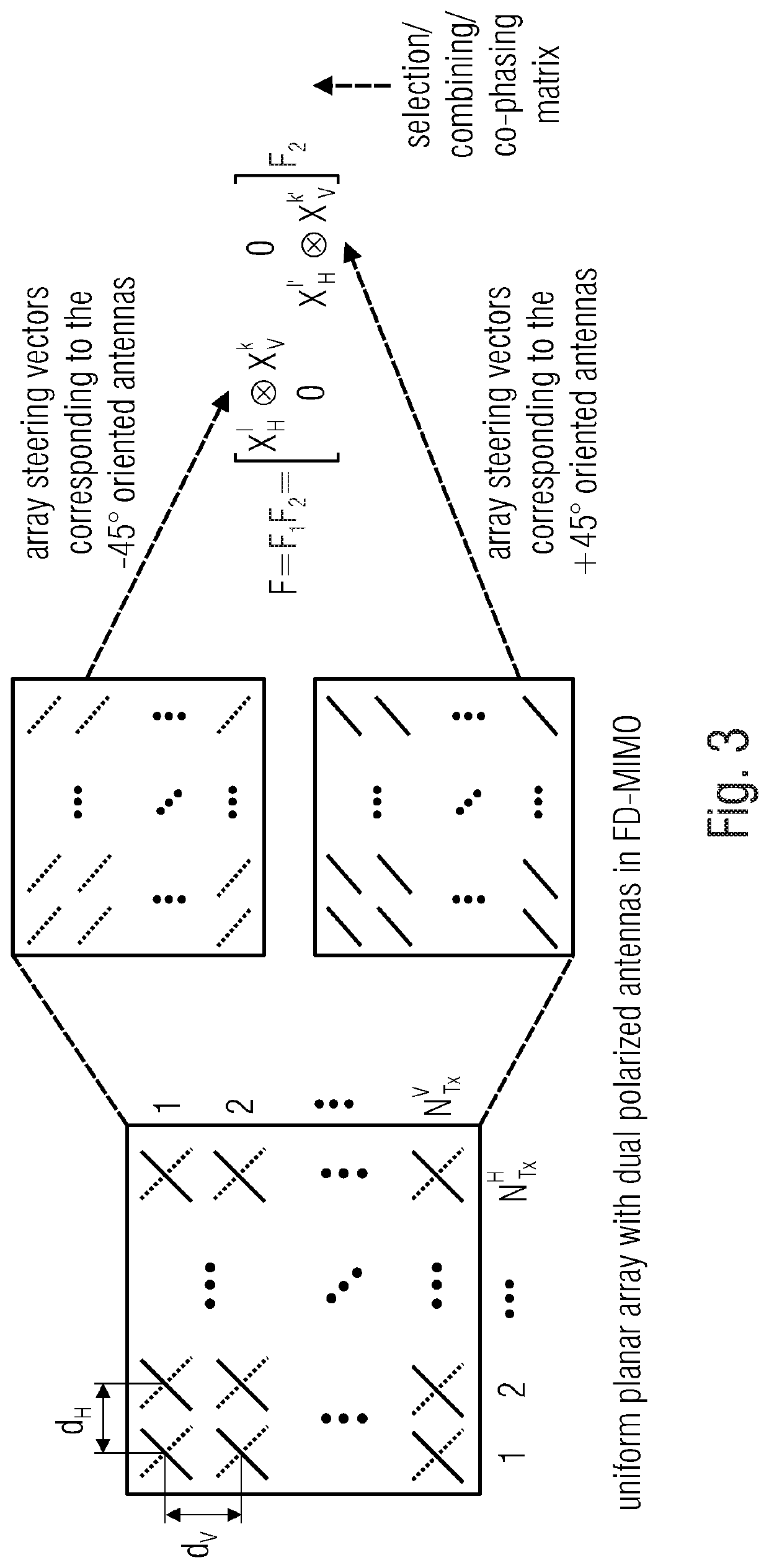
[0046]In the following, embodiments of the present invention are described in further detail with reference to the enclosed drawings in which elements having the same or similar function are referenced by the same reference signs.

[0047]In accordance with embodiments of the present invention in a wireless communication system an antenna array of a transmitter is controlled by a codebook that has been established for a specific antenna array that is different from the transmitter's antenna array. The transmitter's antenna array may be an antenna array having an arbitrary configuration, e.g. the transmitter's antenna array may include a 1-dimensional antenna array, or a 2-dimensional antenna array, or a 3-dimensional antenna array of any array configuration. The specific codebook, e.g. a 2D DFT based codebook, is adapted to the actual or real antenna array of the transmitter by one or more characteristic matrices describing the configuration or nature of the transmitter's antenna array...


PUM


Abstract

A transmitter includes an antenna array having a plurality of antennas for a wireless communication with one or more receivers, and a precoder connected to the antenna array, the precoder to apply a set of beamforming weights to the antenna array, the set of beamforming weights selected from a codebook to form by the antenna array one or more transmit / receive beams or nulls pointing in selected directions. The codebook includes a plurality of sets of beamforming weights for a plurality of directions. The beamforming weights in the codebook are based on a first antenna array response matrix, the first antenna array response matrix defined by a second antenna array response matrix and one or more characteristic matrices. The first antenna array response matrix contains first array response vectors of the antenna array, the second antenna array response matrix contains second array response vectors of another antenna array, the other antenna array being different from the antenna array, and the one or more characteristic matrices describing characteristics of the antenna array.

Description

CROSS-REFERENCE TO RELATED APPLICATIONS[0001]This application is a continuation of copending International Application No. PCT / EP2018 / 052560, filed Feb. 1, 2018, which is incorporated herein by reference in its entirety, and additionally claims priority from European Application No. 17154487.7, filed Feb. 2, 2017, which is also incorporated herein by reference in its entirety.BACKGROUND OF THE INVENTION[0002]The present invention concerns the field of wireless communication systems, such as a mobile communication network. Embodiments of the present invention relate to a multi-antenna technique using a precoder and a codebook with beamforming coefficients adapted to an arbitrary antenna response of a transmitter array. Further embodiments relate to a design of a polarimetric codebook that may be adapted to a 3D antenna response of the transmitter or receiver array, e.g., a 2D DFT codebook for a polarimetric antenna array response. At the receiver, the codebook may be used for a direc...

Claims


Application Information

Patent Timeline
Patent Type & Authority Applications(United States)
IPC IPC(8): H04B7/0456H04B7/06
CPCH04B7/0617H04B7/0486H04B7/0478H04B7/0473H04B7/0619H04B7/0479
Inventor RAMIREDDY, VENKATESHLANDMANN, MARKUSGROSSMANN, MARCUS
Owner FRAUNHOFER GESELLSCHAFT ZUR FOERDERUNG DER ANGEWANDTEN FORSCHUNG EV
Learn More