Optimized dynamic bandwidth scheduler

a dynamic bandwidth scheduler and dynamic bandwidth technology, applied in the field of access networks, can solve the problem of not being able to manage more than 32 onus per dba cycle, and achieve the effect of improving the flexibility of the method

Inactive Publication Date: 2013-11-28
MITSUBISHI ELECTRIC R&D CENTRE EUROPE BV +1
View PDF22 Cites 19 Cited by
  • Summary
  • Abstract
  • Description
  • Claims
  • Application Information

AI Technical Summary

Benefits of technology

[0046]The method according to the invention enables advantageously to allocate timeslots to logical links of ONUs for transmission of data packets by taking into account a required minimum bit rate. Indeed, each logical link can be specific to a given service, which can require different bit rates to obtain a satisfying quality of service. The proposed method suggests to this end defining a state time variable defining a theoretical transmission time for a given logical link. Thus, logical links that are associated with a low required minimal bit rate are not served at each cycle, thus reducing the guard band overhead associated with their upstream transmission. Furthermore, inactive logical links do not send a REPORT message at each cycle, which enables to reduce the control message overhead. The total overhead is thus reduced without reducing the quality of service, given that a minimum bit rate is respected for each logical link.
[0066]This embodiment enables to define different weights for logical links of the same subset, thus improving the flexibility of the method according to the invention.

Problems solved by technology

However, the Multiple-LLIDs method introduces an upstream overhead because of the introduction of additional LLIDs in the EPON architecture.
Referring to the results contained in Table 1, it is not reasonable to manage more than 32 ONUs per DBA cycle.

Method used


Image

  • Optimized dynamic bandwidth scheduler
  • Optimized dynamic bandwidth scheduler
  • Optimized dynamic bandwidth scheduler

Examples


Embodiment Construction

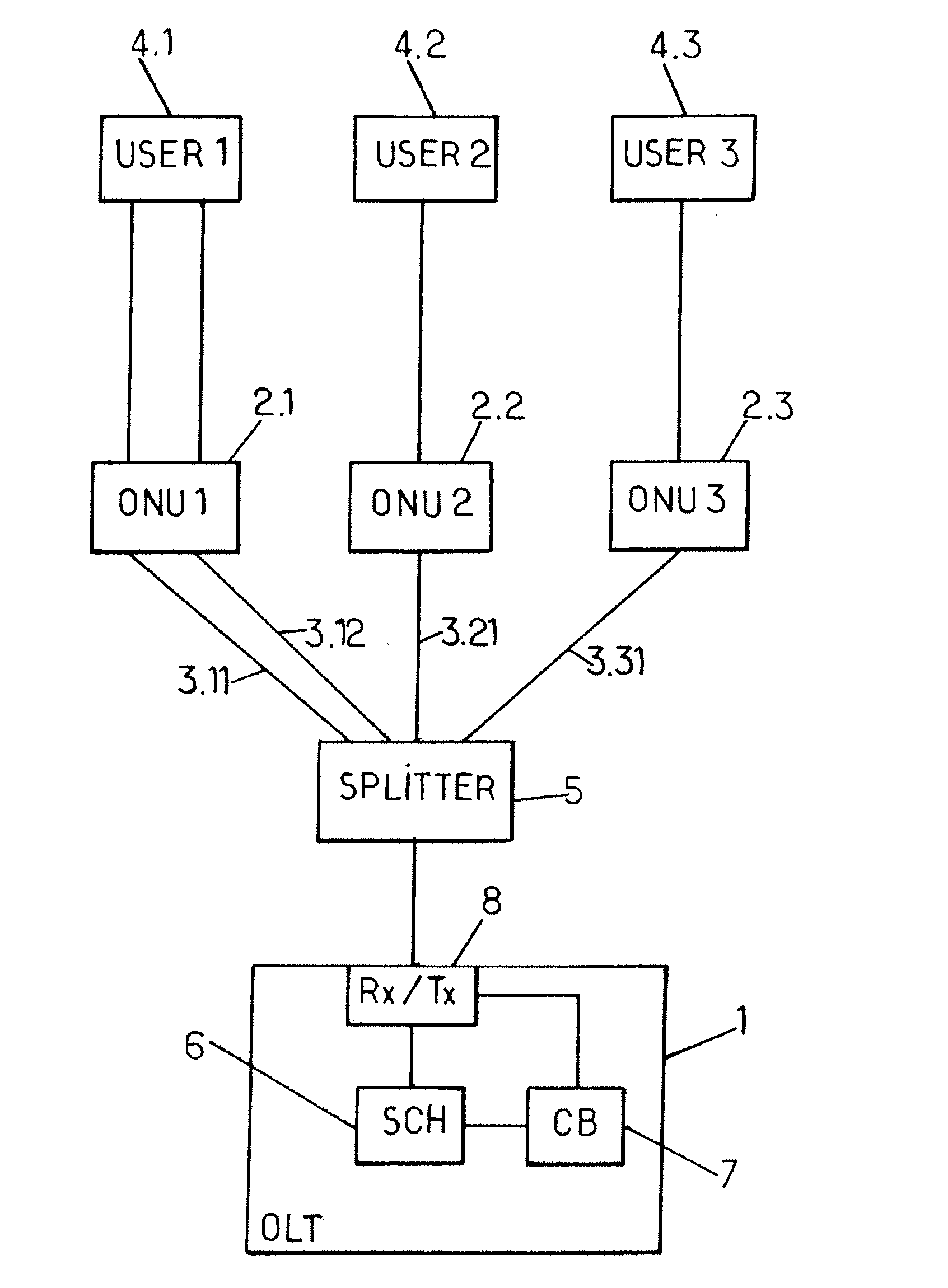
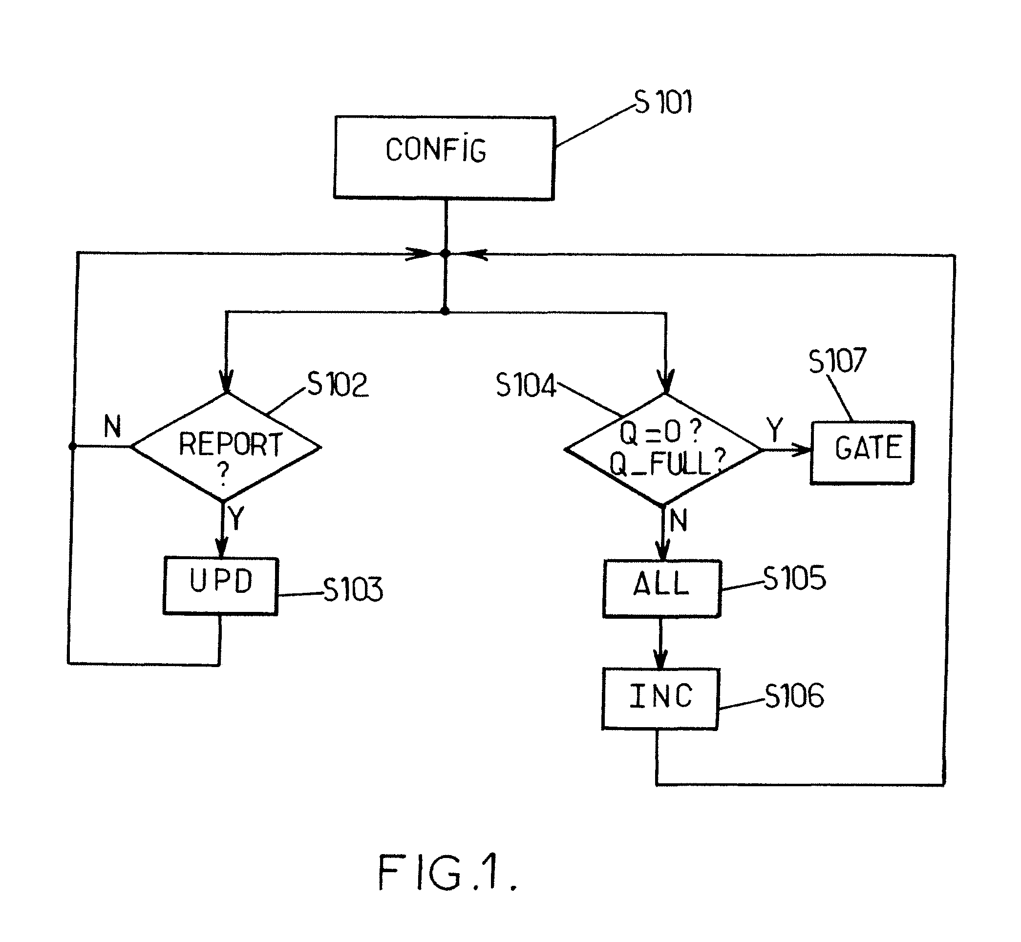
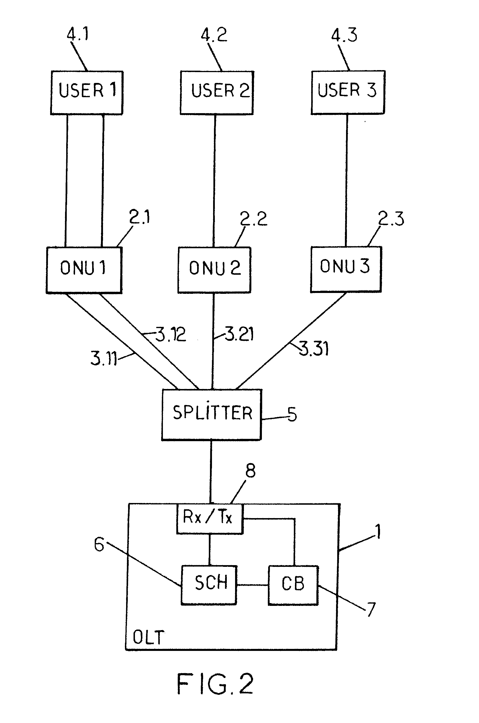
[0081]A solution to reduce the overhead due to REPORT messages and guard band is to reduce the number of logical links LLi scheduled or served in each DBA cycle. Without limiting the total number of logical links LLi supported in the EPON, the method consists in a dynamic assignment of logical link transmission opportunity (or allocation of timeslots in a given DBA cycle) instead of the legacy assignment presented in the part relating to the state of the art.

[0082]Such a solution leads to reduce the overhead. To avoid obtaining an unfair queuing scheme, because this solution increases the upstream transmission time, given that ONUs shall wait several cycles before having timeslots allocated to them, the invention introduces for each logical link LLi a next time emission value TTTi that guarantees fairness among the different logical links LLi.

[0083]Thus at each cycle k, a trace of how were served the logical links LLi in the past is maintained so that the same logical links LLi are ...


PUM


Abstract

A method allocating timeslots for transmission of data packets and REPORT messages in a communication network including plural logical links managed by a terminal, including: implemented at each cycle by the terminal receiving at least one REPORT message from at least one logical link, the REPORT message including an updated queue length expressed in timeslots of the logical link and, upon receiving the REPORT message, updating the image queue length, based on the updated queue length; allocating to logical links having non-zero image queue length at least one timeslot in a next cycle based on a theoretical transmission time for transmitting data packets or REPORT messages and based on a fraction of overhead associated with the transmission, until all timeslots of the next cycle are allocated or all image queue lengths are zero, and incrementing the theoretical transmission time of each logical link based on its required minimum bit rate.

Description

BACKGROUND OF THE INVENTION[0001]1. Technical Field[0002]The present invention generally relates to access networks and more precisely to Passive Optical Networks (PON).[0003]It finds applications, in particular, in Ethernet Passive Optical Networks (EPON) for point to multi-point communications between a terminal and a plurality of units.[0004]2. Related Art[0005]The approaches described in this section could be pursued, but are not necessarily approaches that have been previously conceived or pursued. Therefore, unless otherwise indicated herein, the approaches described in this section are not prior art to the claims in this application and are not admitted to be prior art by inclusion in this section.[0006]A PON is a single, shared optical fiber that uses inexpensive optical splitters to divide the single fiber from a Central Office (CO) into separate strands feeding individual subscribers. In such networks, information is carried by laser bursts. PONs are called ‘passive’ becau...

Claims


Application Information

Patent Timeline
Patent Type & Authority Applications(United States)
IPC IPC(8): H04B10/27
CPCH04B10/27H04Q11/0001H04L49/90H04L12/4035H04L45/14H04L41/08
Inventor ROLLET, ROMAIN
Owner MITSUBISHI ELECTRIC R&D CENTRE EUROPE BV
Why Eureka
Try Eureka