Method for optimizing beam forming matrix for multi-base station collaboration system

A beamforming matrix and cooperative system technology, applied in diversity/multi-antenna systems, space transmit diversity, preventing/detecting errors through diversity reception, etc., can solve problems such as considering cooperative processing methods and affecting system performance

Inactive Publication Date: 2011-03-16
SHANGHAI JIAO TONG UNIV
View PDF3 Cites 23 Cited by
  • Summary
  • Abstract
  • Description
  • Claims
  • Application Information

AI Technical Summary

Problems solved by technology

However, there are two major problems in the realization of multi-cell cooperation technology: in order to realize the cooperation between base stations, the network background needs a large backhaul capacity to complete the information exchange between base stations; The degree of channel state information is also an important factor affecting system performance
[0005] However, this prior art seldom considers the choice of cooperative processing based on the overhead of the system

Method used


Image

  • Method for optimizing beam forming matrix for multi-base station collaboration system
  • Method for optimizing beam forming matrix for multi-base station collaboration system
  • Method for optimizing beam forming matrix for multi-base station collaboration system

Examples


Embodiment 1

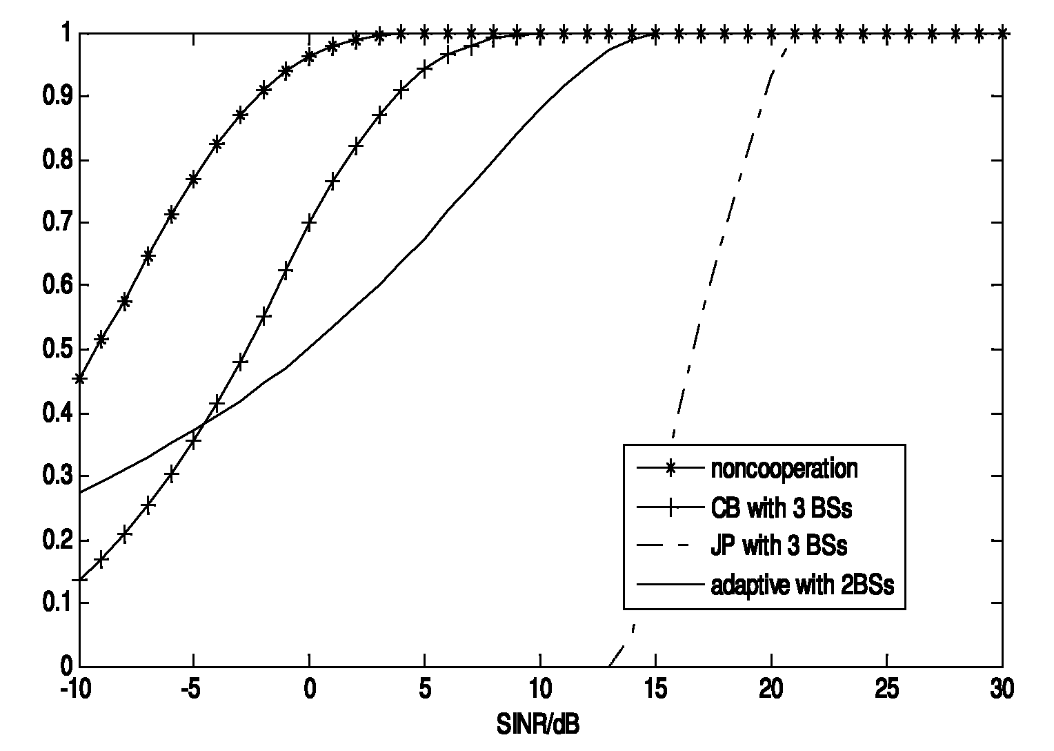
[0063] Such as figure 2 shown, for figure 2 The figure shows that in the multi-base station cooperative system, the number of base stations is 3, each base station uses 4 antennas, each cell randomly distributes 2 users, each user uses 1 antenna, and the number of data streams for each user is 1. Under the condition that the signal-to-noise ratio is 15dB, the statistical distribution of the number of users of the signal-to-dry ratio varies with the power, and the simulation compares the multi-cell system with no coordination between cells and the multi-cell system with coordinated beamforming technology between base stations. And the statistical distribution of the instantaneous sinr of the system users using the joint transmission technology between base stations. For the cooperative selection method between base stations proposed in the present invention, by figure 2 It can be seen that although the selection method proposed by the present invention is limited by the nu...

Embodiment 2

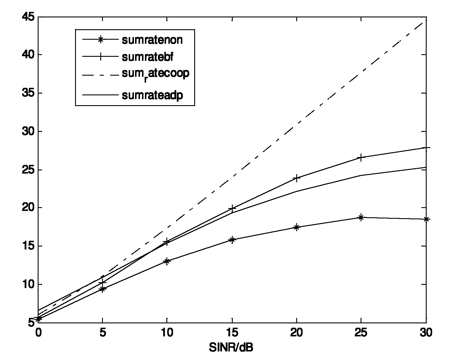
[0065] Such as image 3 As shown, the number of base stations in the multi-base station cooperative system is 3, each base station uses 4 antennas, each cell randomly distributes 2 users, each user uses 1 antenna, and the number of data streams for each user is 1. The average capacity of the system varies with power, and the system capacity of the multi-cell system with no coordination between cells, the multi-cell system with coordinated beamforming technology between base stations, and the system with joint transmission technology between base stations is compared by simulation. For the selection method of the cooperation mode between base stations of the present invention, by image 3 It can be seen that the algorithm proposed by the present invention has lower system capacity than the cooperative algorithm based on all base stations participating, but when the signal-to-noise ratio is small, the present invention has better system capacity than the coordinated algorithm ob...


PUM


Abstract

The invention relates to a method for optimizing a beam forming matrix for a multi-base station collaboration system in the technical field of wireless communication. In the method, a distributed base station collaboration selection mode is adopted and a collaboration base station is selected at a client according channel state information and a related interference channel; a user can select whether to require the base station to be collaborated with an adjacent base station to carry out collaboration transmission and simultaneously selects a base station which causes larger interference to the user to carry out collaboration according to channel gain of the base station and interference channel gain; and the base station determines a finally selected collaborated mode in the principle of highest service quality according to feedback information so as to realize the balance of the service quality requirements between the users.

Description

technical field [0001] The present invention relates to a method in the technical field of wireless communication, in particular to an optimization method for a beamforming matrix used in a multi-base station cooperative system. Background technique [0002] Downlink multi-base station cooperation technology can effectively eliminate inter-cell interference, improve system fairness and increase system spectrum efficiency. However, there are two major problems in the realization of multi-cell cooperation technology: in order to realize the cooperation between base stations, the network background needs a large backhaul capacity to complete the information exchange between base stations; The degree of channel state information is also an important factor affecting system performance. Therefore, how to effectively design the beamforming matrix to reduce inter-cell interference and improve system capacity is one of the main research topics in the current multi-cell cooperative ...

Claims


Application Information

Patent Timeline
Patent Type & Authority Applications(China)
IPC IPC(8): H04B7/04H04L1/06
Inventor 林意如吴幼龙罗汉文俞晖
Owner SHANGHAI JIAO TONG UNIV
Why Eureka
Try Eureka