Picture encoding system conversion device and encoding rate conversion device

a technology of encoding system and conversion device, which is applied in the field of picture encoding system conversion device and encoding rate conversion device, can solve the problems of lowering service quality, reducing the service life of the device, and failing to take the time delay into account, so as to reduce the effect of picture quality deterioration and delay tim

Inactive Publication Date: 2001-07-19
NEC CORP
View PDF2 Cites 22 Cited by
  • Summary
  • Abstract
  • Description
  • Claims
  • Application Information

AI Technical Summary

Benefits of technology

[0020] However, in the picture encoding system conversion used in real-time communication, time delay caused in the encoding system conversion brings about a lowered service quality.
[0028] With a simple encoder, it is possible to calculate an optimum volume of bit allocation to each frame from the band of the transmission channel for transmitting the bitstream and from the picture sampling interval.
[0032] It is therefore an object according to an aspect of the present invention to provide a picture encoding system conversion device and an encoding rate conversion device in which delay time increase or picture quality deterioration may be decreased.
[0033] It is another object according to another aspect of the present invention to provide a novel picture encoding system conversion device and an encoding rate conversion device, which can make best use of the information on the code volume such as that of encoding parameters, input buffer, output buffer, input bitstream or the output bitstream, and in which picture encoding system conversion and code rate conversion can be realized taking realtime conversion into consideration.

Problems solved by technology

However, in the picture encoding system conversion used in real-time communication, time delay caused in the encoding system conversion brings about a lowered service quality.
On the other hand, the conventional encoding rate conversion device, while stating the method for determining the quantization step, fails to take the time delay into account.
The above-described conventional devices suffer the following problems:

Method used


Image

  • Picture encoding system conversion device and encoding rate conversion device
  • Picture encoding system conversion device and encoding rate conversion device
  • Picture encoding system conversion device and encoding rate conversion device

Examples


first embodiment

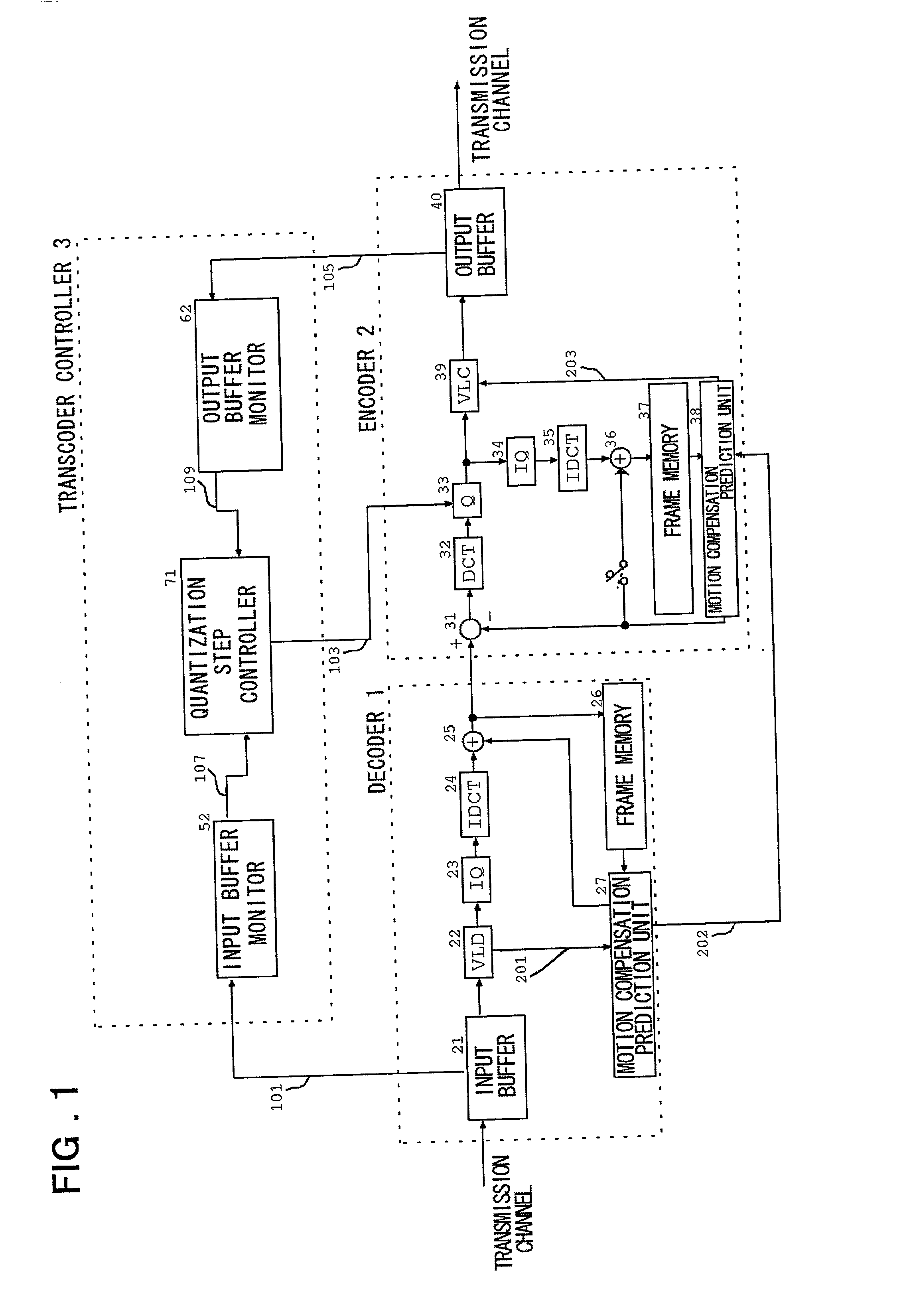
[0055] In the following, preferred embodiments of the present invention are explained. Referring to FIG. 1, a picture encoding system conversion device according to the present invention includes a decoder 1 for receiving picture codes, compressed in information volume, from a reception side transmission channel via an input buffer 21 and for expanding the received picture codes to output expanded picture codes. An encoder 2 compresses the picture signals, decoded by said decoder, in information volume, to generate picture codes to output the generated picture codes from an output buffer 40 to a sending out side transmission channel. A transcoder controller 3 includes input buffer monitor 52 for monitoring said input buffer 21 of the decoder 1 and output buffer monitor 62 for monitoring the output buffer of the encoder 2. There is also provided a quantization step controller 71 for modifying the quantization step in the compression processing of the encoder 2 based on the informatio...

second embodiment

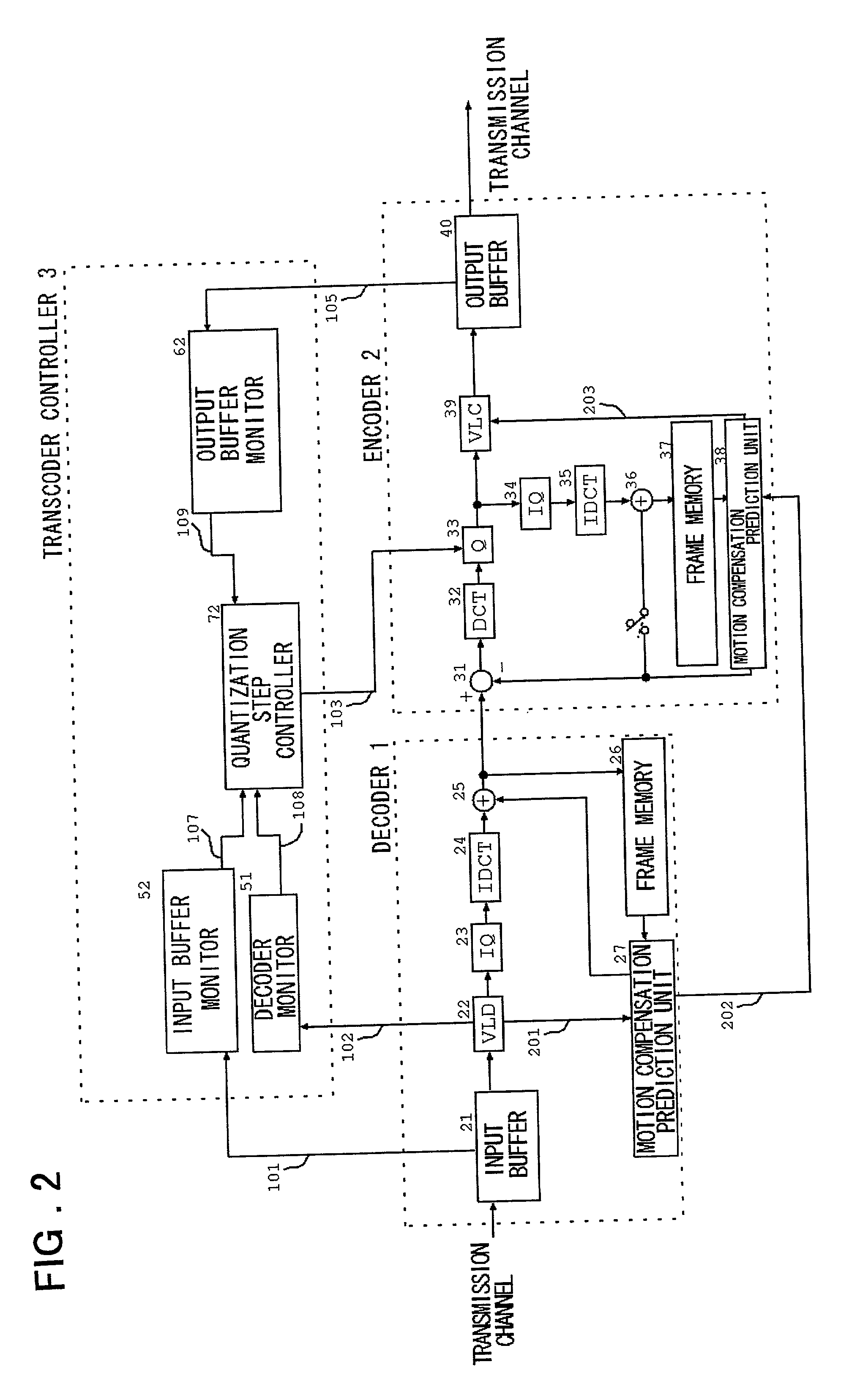
[0056] Referring to FIG. 2, a code rate conversion device of the present invention includes a decoder 1 for receiving picture codes compressed in information volume from a reception side transmission channel by an input buffer 21 and for subsequently sending out the decoded picture codes through an output buffer 40 to a sending out side transmission channel. A transcoder controller 3 includes a decoder monitor 51 for monitoring the VLD unit 22 of the decoder 1, an input buffer monitor 52 for monitoring the input buffer 21 of the decoder 1, and an output buffer monitor 62 for monitoring the output buffer 40 of the encoder 3. There is also provided a quantization step controller 72 for modifying the quantization step in the compression processing of the code rate conversion unit based on the information from the input buffer monitor and from the output buffer monitor.

third embodiment

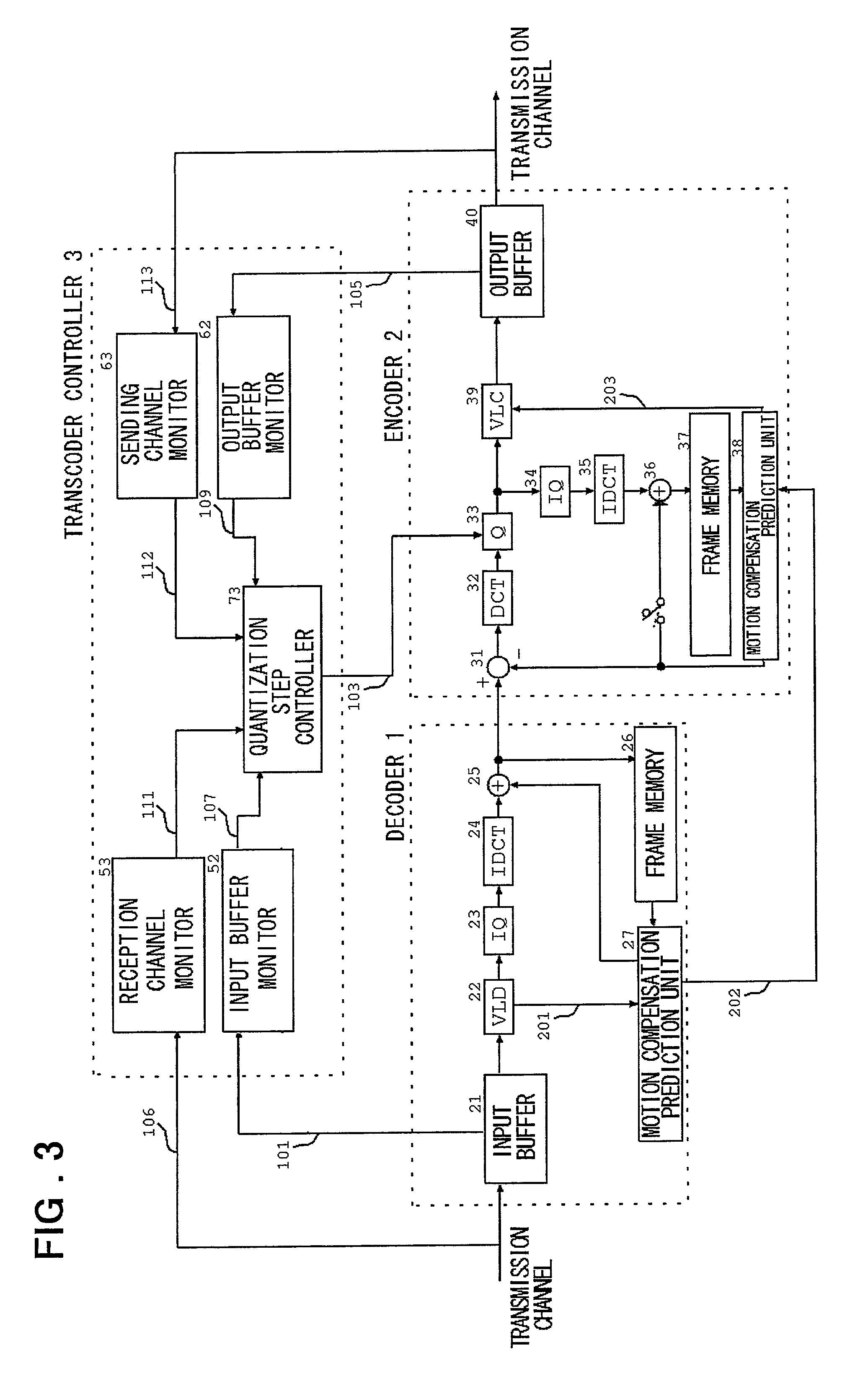
[0057] Referring to FIG. 3, an encoding system conversion device for converting a signal encoded in one encoding system into a signal of another encoding system, according to the present invention, includes a decoder 1 for receiving a compression-coded signal in an input buffer 21 to decode the signal in a variable length decoder 22 to output picture signals. An encoder 2 is fed with a signal output from the decoder 1 to compress the information to output the information to a sending out transmission channel via an output buffer 40. A transcoder controller 3 has an input buffer monitor 52 for monitoring the input buffer 21 of the decoder 1, an output buffer monitor 62 for monitoring the output buffer 40 of the encoder 2, a reception transmission channel monitor 53 for monitoring the state of the reception transmission channel and a sending out transmission channel monitor 63 for monitoring the state of the sending out transmission channel. There is also provided a quantization step ...


PUM


Abstract

A picture encoding system conversion device and a code rate conversion device for realizing the conversion taking into account both time delay and picture quality using the information on the code volume of the encoding parameters, input and output buffers and an input bitstream. There are provided a decoder 1 including an input buffer 21, a VLD unit 22, an inverse quantizer 23, an IDCT unit 24, an adder 35, a frame memory 26 and a motion compensation prediction unit 27; an encoder 2 including an adder 31, a DCT unit 32, a quantizer 33, an inverse quantizer 34, an IDCT unit 35, an adder 36, a frame memory unit 37, a motion compensation prediction unit 38, a VLD unit 39 and an output buffer 40; and a transcoder controller 3 including a decoder monitor unit 51, an input buffer monitor unit 52, a reception transmission channel monitor 53, a sending transmission channel monitor 63, an output buffer monitor unit 62 and a quantization step controller 74. The quantization step controller 74 modifies the quantization step of the encoder based on the information from the input buffer monitor, output buffer monitor, decoder monitor, reception transmission channel monitor and sending transmission channel monitor.

Description

[0001] This invention relates to a picture (or image) encoding system conversion device and encoding rate conversion device and, more particularly, to a device which performs rate control taking both the picture quality and time delay accompanying the conversion into account.[0002] In a digital picture (or image) communication system or a digital picture communication service, the technique of encoding the picture information to reduce the information volume to effect transmission and storage is used in transmitting and storing the picture information. As an encoding system for moving picture, internationally standardized by ITU-T(lnternational Telecommunication Union), there are known an encoding system prescribed by H. 261 Recommendations providing for standardization of transmitted pictures of visual telephone and video conference and H. 263 Recommendations providing for standardization of pictures transmitted over a low bitrate network, such as PHS (Personal Handy-Phone System)....

Claims


Application Information

Patent Timeline
Patent Type & Authority Applications(United States)
IPC IPC(8): F28F1/32G06T9/00H03M7/30H04N7/24H04N19/00H04N19/126H04N19/15H04N19/166H04N19/40H04N19/423H04N19/503H04N19/61H04N19/625H04N19/91H04N21/234H04N21/44
CPCH04N21/23406H04N21/44004H04N19/172H04N19/15H04N19/61H04N19/124H04N19/152H04N19/40
Inventor ISHIYAMA, KIYOSHI
Owner NEC CORP
Why Eureka
Try Eureka