Apparatus and Method for Multi-Protocol Label Switching Label-Switched Path Protection Switching

Inactive Publication Date: 2008-12-25
ELECTRONICS & TELECOMM RES INST
View PDF13 Cites 21 Cited by
  • Summary
  • Abstract
  • Description
  • Claims
  • Application Information

AI Technical Summary

Benefits of technology

[0021]The apparatus and method for multi-protocol label switching (MPLS) label-switched path (LSP) protection switching have the following effects. The apparatus and method make up the MPLS LSP of the working LSP and the protection LSP according to a 1:1 mode, and can perform protection switching within 50 ms, thus capable of preventing quality of service from deteriorating and improving availability of an MPLS network up to a level of synchronous d

Problems solved by technology

However, in the case of a multi-protocol label switching (MPLS) label-switched path (LSP), since there is no such technology capable of performing protection switching in a physical layer, it is hard to perform the protection switching within 50 ms.
Therefore, according to conventional MPLS technology, when a failure occurs on an LSP, availability of the LSP deteriorates, so that it is not possible to ensure signal quality of traffic transmitted through the LSP.
When the failure occurs, the protection switching is not rapidly performed on the LSP on which the failure occurs.

Method used


Image

  • Apparatus and Method for Multi-Protocol Label Switching Label-Switched Path Protection Switching
  • Apparatus and Method for Multi-Protocol Label Switching Label-Switched Path Protection Switching
  • Apparatus and Method for Multi-Protocol Label Switching Label-Switched Path Protection Switching

Examples


Example

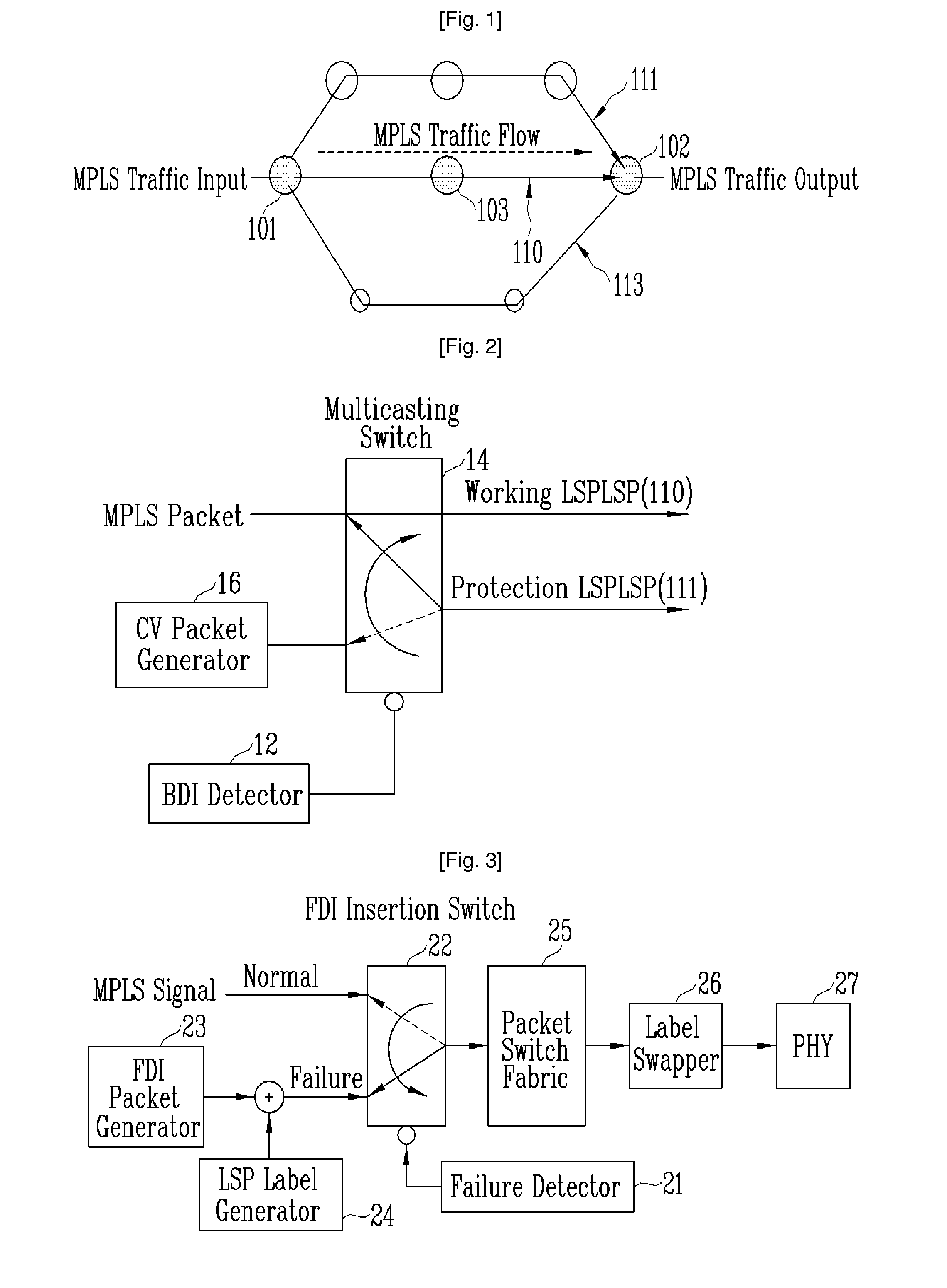
[0048]FIG. 3 is a block diagram illustrating a first embodiment of inserting an FDI signal at a transit node when a failure occurs on an MPLS LSP, according to the present invention.

[0049]Referring to FIG. 3, when a failure occurs between the ingress node 101 and the transit node 103, the failure is detected, and the FDI signal is inserted by the transit node 103 in a hardware way.

[0050]More specifically, when no failure occurs on the MPLS LSP, the FDI insertion switch 22 selects a “normal” state, so that an MPLS packet is switched by the packet switching fabric 25. Then, the MPLS packet is subjected to label swapping by the label swapper 26 and transmitted to the next node through the PHY 27.

[0051]However, when the failure occurs on the MPLS LSP, the failure detector 21 controls the FDI insertion switch 22 to select a “failure” state. Here, the FDI packet generator 23 generates an FDI / BDI OAM packet at periods of 3 ms or less, as shown in FIG. 6. The LSP label generator 24 generate...

Example

SECOND EMBODIMENT

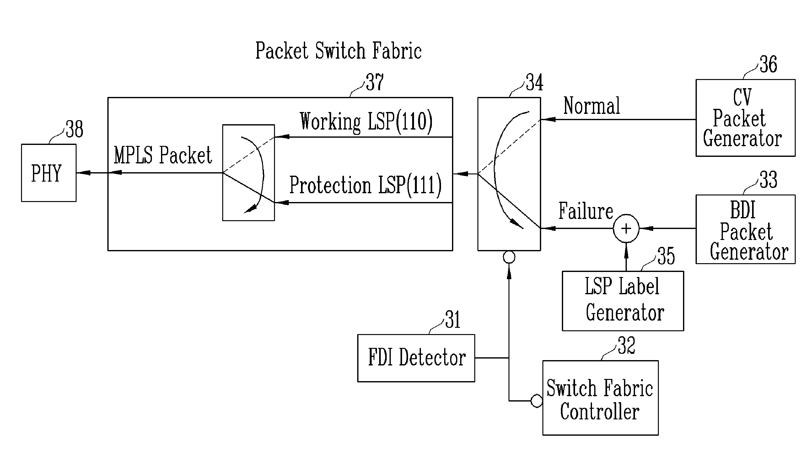
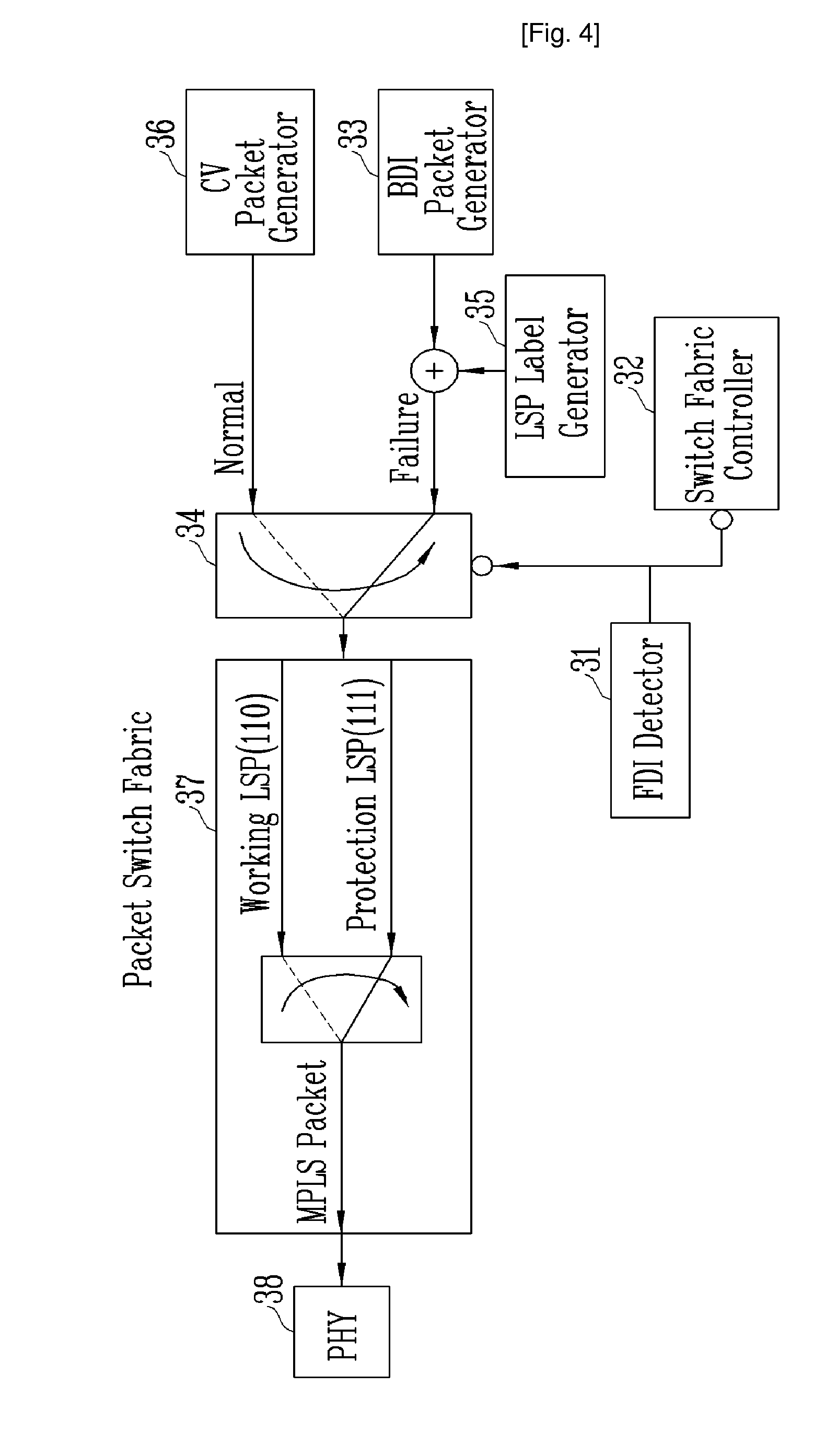
[0058]FIG. 4 is a block diagram showing an embodiment of inserting FDI in a BDI packet at an egress node, according to the present invention.

[0059]Referring to FIG. 4, the FDI detector 31 receives an MPLS packet that is transmitted from the transit node 103 as in the first embodiment, and detects an FDI packet. Here, when the FDI packet is detected by the FDI detector 31, it is recognized that a failure occurs at the transit node 103. Thereby, the BDI insertion switch 34 is controlled.

[0060]More specifically, in a normal state, the BDI insertion switch 34 selects an output signal of the CV packet generator 36 in order to monitor a connection state of the return path 113. Here, the CV packet generator 36 periodically generates the CV or FFD packet, and sets the generation period of the CV to a time 1 sec and that of the FFD from 10 ms to 500 ms adjusted by 10 ms.

[0061]The BDI packet generator 33 generates a packet as shown in FIG. 6. Here, a defect location (DL) ind...

Example

THIRD EMBODIMENT

[0078]FIG. 2 illustrates an embodiment of multicasting an MPLS packet to a working LSP and a protection LSP at an ingress node according to the present invention.

[0079]Referring to FIG. 2, the BDI detector 12 receives a BDI OAM packet transmitted from the egress node 102 as in Second Embodiment, and detects a BDI packet. Here, when the BDI packet is detected by the BDI detector 12, it is determined that the failure occurs at the egress node 102. Thereby, the multicasting switch 14 is controlled to multicast an MPLS packet to the working LSP 110 and the protection LSP 111, thus performing a protection switching function related to a transmission unit.

[0080]By using the multicasting switch 14 in this way, the same effect as in a 1:1 switching method of synchronous digital hierarchy (SDH) / synchronous optical network (SONET) that bridges traffic to be protected to a working link and a protection link is obtained.

[0081]FIG. 9 is a flowchart illustrating a process of cont...


PUM


Abstract

Provided are system and method for multi-protocol label switching (MPLS) label-switched path (LSP) protection switching in an MPLS system employing a working LSP and a protection LSP in a 1:1 mode, the apparatus and method prepare a dedicated LSP for one working LSP and are capable of rapidly processing a forward defect indication (FDI)/backward defect indication (BDI) signal when a failure occurs on the working LSP. The system includes: an ingress node multicasting input MPLS traffic through the working LSP and the protection LSP using a fed-back BDI signal; a transit node relaying the MPLS traffic input from the ingress node, and generating a FDI signal when the failure occurs; and an egress node extracting the MPLS traffic from the MPLS LSP input from the transit node, and when the FDI signal is detected, inserting and feeding back the BDI signal to the ingress node through a return path and performing switching to the protection LSP.

Description

TECHNICAL FIELD[0001]The present invention relates to an apparatus and method for multi-protocol label switching (MPLS) label-switched path (LSP) protection switching, and more particularly, to an MPLS LSP protection switching apparatus and method for an MPLS LSP in a 1:1 mode, and when a failure occurs on the LSP, performing protection switching on a path on which the failure occurs.BACKGROUND ART[0002]Protection switching technology has been mainly applied to synchronous digital hierarchy (SDH) / synchronous optical networking (SONET) that is a synchronous optical transmission apparatus. Further, in the SDH / SONET, there is ring protection switching technology having a self-healing function such as unidirectional path switched ring (UPSR) and bidirectional line switched ring (BLSR), as well as line protection switching technology that operates in a point-to-point mode such as a 1:1 mode and a 1:N mode.[0003]In general, the protection switching technology applied to the SDH / SONET mini...

Claims


Application Information

Patent Timeline
IPC IPC(8): H04L12/24H04L45/586H04L45/247
CPCH04L41/0668H04L43/0811H04L45/22H04L45/28H04L45/50H04L12/28H04L45/00
Inventor CHUN, KYUNG GYULEE, SOON SEOK
Owner ELECTRONICS & TELECOMM RES INST
Why Eureka
Try Eureka