Debug information collection method and debug information collection system

a technology of information collection and information collection, applied in error detection/correction, instruments, computing, etc., can solve the problems of large number of devices involving a large amount of time, limited probe insertion range, memory resources and overhead of execution time, etc., to speed up the failure-cause analysis of distributed software and reduce the load on the device side. , the effect of reducing the load

Inactive Publication Date: 2008-06-12
HITACHI LTD
View PDF9 Cites 17 Cited by
  • Summary
  • Abstract
  • Description
  • Claims
  • Application Information

AI Technical Summary

Benefits of technology

[0021]According to the present invention, it is possible to reduce a load on the device side and a lo

Problems solved by technology

In the patent document 1, a probe insertion range is limited; also, memory resources and the overhead of the execution time are limited.
However, repeatedly collecting information from a large number of devices involves a large amount of time, which is a problem to be solved.
Further, in the nonpatent document 1, because a range of probes used to acquire information is limited by use of random numbers, the overhead of the execution time is limited.
However, because all probes are inserted into a program beforehand, the overhead given to memory resources is large, which is a problem to be solved.
To be more s

Method used


Image

  • Debug information collection method and debug information collection system
  • Debug information collection method and debug information collection system
  • Debug information collection method and debug information collection system

Examples


Embodiment Construction

[0028]Embodiments of the present invention will be described with reference to the drawings as below.

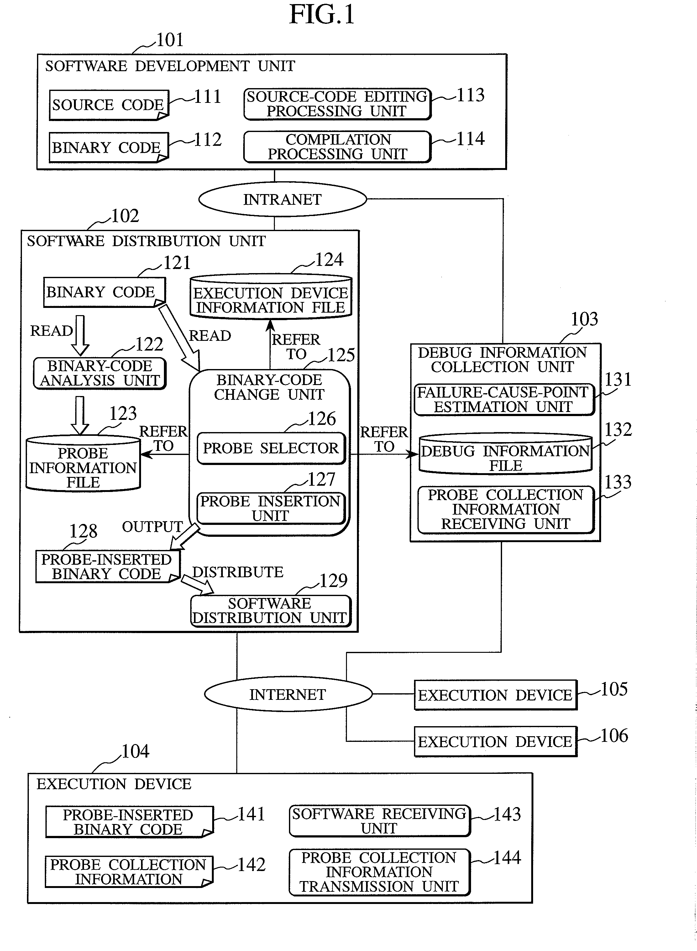
[0029]FIG. 1 is a diagram illustrating an embodiment of a software distribution system according to the present invention. This software distribution system includes a software development unit 101, a software distribution unit 102, a debug information collection unit 103, and a plurality of execution devices (devices) 104, 105, and 106. First of all, how these units are associated with one another will be described.

[0030]A software developer uses the software development unit 101 to develop software so that executable binary code is generated. The generated binary code is transmitted to the software distribution unit 102 through an intranet, or the like. The software distribution unit 102 inserts probes into the binary code, before distributing the binary code to the execution devices 104, 105, and 106 through the Internet, or the like. Each of the execution devices executes the dis...


PUM


Abstract

In a software distribution unit, a binary-code analysis unit determines a total set of insertion positions at which probes can be inserted into software. A binary-code change unit determines the population of insertion positions of probes to be inserted into the software and the number of insertion positions of probes to be inserted on a device basis. Then, the binary-code change unit selects, from the population, insertion positions of probes as many as the determined number of insertion positions and inserts the probes into the software at the selected insertion positions. A software distribution unit distributes, to the device, the software into which the probes are inserted. As a result, it is possible to reduce both a load on the device side and a load on the software developer side at the same time and to acquire uniform debug information without deviations.

Description

CLAIM OF PRIORITY[0001]The present application claims priority from Japanese application serial no. JE 2006-325922, filed on Dec. 1, 2006, the content of which is hereby incorporated by reference into this application.BACKGROUND OF THE INVENTION[0002]The present invention relates to a method for collecting debug information of software that is particularly distributed to a large number of devices connected through networks so that the software is executed by each of the devices, the debug information being used to improve the quality of the software.[0003]Software size is increasing in information processing equipment, which is so-called built-in equipment. The information processing equipment includes home information appliances and portable telephones. The reason the software size is increasing in the information processing equipment is that manufacturers are required to achieve many new functions by use of software in a short period of time as a result of the addition of network-...

Claims


Application Information

Patent Timeline
IPC IPC(8): G06F11/36
CPCG06F11/362G06F11/28G06F11/30
Inventor KAWASAKI, SHINICHIRONOJIRI, TORU
Owner HITACHI LTD
Why Eureka
Try Eureka