Data transmission control method and apparatus, and terminal

a data transmission control and terminal technology, applied in multiplex communication, synchronisation arrangement, transportation and packaging, etc., can solve the problems of poor stability, low channel utilization, inefficient data transmission process, etc., and achieve the effect of improving data transmission efficiency and channel utilization

Active Publication Date: 2019-11-14
AUTEL UNITED CREATION SOFTWARE DEV CO LTD +1
View PDF0 Cites 3 Cited by
  • Summary
  • Abstract
  • Description
  • Claims
  • Application Information

AI Technical Summary

Benefits of technology

[0033]During data transmission between a master terminal and a plurality of slave terminals, the master terminal performs a timing negotiation with the slave terminals to obtain timings allocated for the slave terminals. Upon completion of timing allocation, the master terminal sends interactive data by means of broadcasting. When responses of the respective slave terminals to the received interactive data according to the allocated corresponding timings are received, completion of transmission of the interactive data to the slave terminals is acknowledged using the received responses. During the data transmission, the master terminal only needs to send interactive data once, and upon receiving of the interactive data, the respective slave terminals make responses in a polling manner according to the allocated timings, thereby improving the data transmission efficiency and the channel utilization.

Problems solved by technology

When data needs to be wirelessly transmitted to a plurality of terminals, one-to-multiple transmission by the same frequency and in the same channel may likely cause interference, resulting in poor stability.
However, the entire data transmission process is inefficient, and the channel utilization is low, especially for the one-to-multiple data transmission process used in the technical area of tire pressure sensor.
Specifically, when a special services tool as a master terminal needs to transmit data to multiple tire pressure sensors (as slave terminals) in the car, it is inefficient to transmit data by the method of the art.

Method used


Image

  • Data transmission control method and apparatus, and terminal
  • Data transmission control method and apparatus, and terminal
  • Data transmission control method and apparatus, and terminal

Examples


Embodiment Construction

[0050]The description will be made in detail herein with respect to exemplary embodiments, examples of which are illustrated in the accompanying drawings. Implementation manners described in the following exemplary embodiments do not represent all implementation manners consistent with this application. Instead, they are merely examples of apparatuses and methods consistent with aspects of this application as detailed in the appended claims.

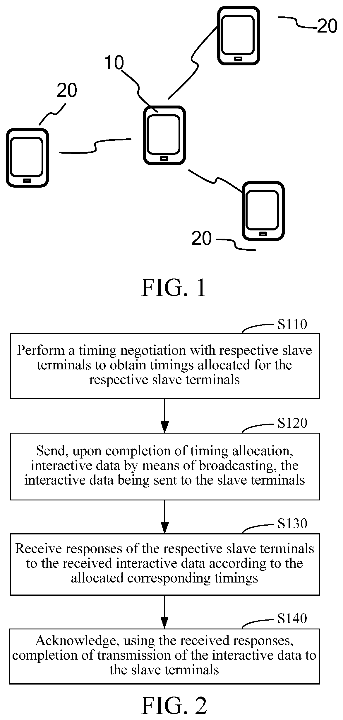
[0051]FIG. 1 is a schematic diagram of an implementation environment according to this application. As shown in FIG. 1, the implementation environment includes a master terminal 10 and a plurality of slave terminals 20 that perform mutual data transmission with the master terminal 10. The master terminal 10 and the plurality of slave terminals 20 perform a timing negotiation respectively, thereby performing data transmission. The master terminal 10 and the plurality of slave terminals 20 are communicatively connected in a wireless manner, such as...


PUM


Abstract

A data transmission control method and apparatus, and a terminal are disclosed. The method includes: performing, by a master terminal, a timing negotiation with respective slave terminals to obtain timings allocated to the respective slave terminals; sending, upon completion of timing allocation, interactive data by means of broadcasting, the interactive data being sent to the slave terminals; receiving responses of the respective slave terminals to the received interactive data according to the allocated corresponding timings; and acknowledging, using the received responses, completion of transmission of the interactive data to the slave terminals. The data transmission control method and apparatus and the terminal can be used to improve data transmission efficiency and channel utilization.

Description

[0001]This application claims priority to and benefits of Chinese Patent Application No. 201611225959.0, filed with the State Intellectual Property Office of P. R. China on Dec. 27, 2016. The entire content of the above-referenced application is incorporated herein by reference.BACKGROUNDTechnical Field[0002]This application relates to the technical field of wireless communications, and in particular, to a data transmission control method and apparatus, and a terminal.Related Art[0003]With the development of radio, wireless data transmission is very widely applied. At present, one-to-one transmission is usually used, that is, data is transmitted to another terminal by the same frequency and in the same channel.[0004]When data needs to be wirelessly transmitted to a plurality of terminals, one-to-multiple transmission by the same frequency and in the same channel may likely cause interference, resulting in poor stability. At present, in the case of one-to-multiple data transmission, ...

Claims


Application Information

Patent Timeline
Patent Type & Authority Applications(United States)
IPC IPC(8): H04W56/00H04W76/40B60C23/04
CPCH04W76/40B60C23/0455H04W56/003H04W84/20H04W56/005H04J3/16H04L1/0006B60C23/0471B60C23/0479
Inventor WU, YONG
Owner AUTEL UNITED CREATION SOFTWARE DEV CO LTD
Why Eureka
Try Eureka