Dilation Device

a technology of inflatable zone and dilator, which is applied in the direction of balloon catheter, catheter, surgery, etc., can solve the problem of reducing the radial protrusion of the inflatable zon

Active Publication Date: 2019-11-21
TEVAR PTY LTD
View PDF0 Cites 2 Cited by
  • Summary
  • Abstract
  • Description
  • Claims
  • Application Information

AI Technical Summary

Benefits of technology

[0036]Optionally, a collar may be associated with each intermediate zone, which collars inhibit radial expansion of the intermediate zones in the region of the collars during inflation of the inflatable tube, and radial collapse of the intermediate zones in the region of the collars during deflation of the inflatable tube under partial vacuum.

Problems solved by technology

A drawback of prior art inflatable dilatators is that, when the inflatable zones of inflated tubes are subjected to a partial vacuum, each inflatable zone collapse radially, reducing the radial protrusion of the inflatable zone from the longitudinal axis of the inflatable zone more than the longitudinal axial length of the inflatable zone.

Method used


Image

  • Dilation Device
  • Dilation Device
  • Dilation Device

Examples


Embodiment Construction

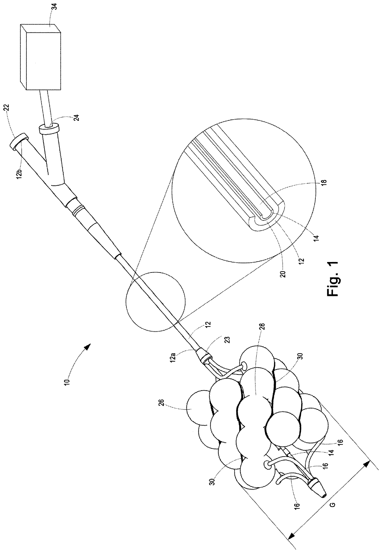
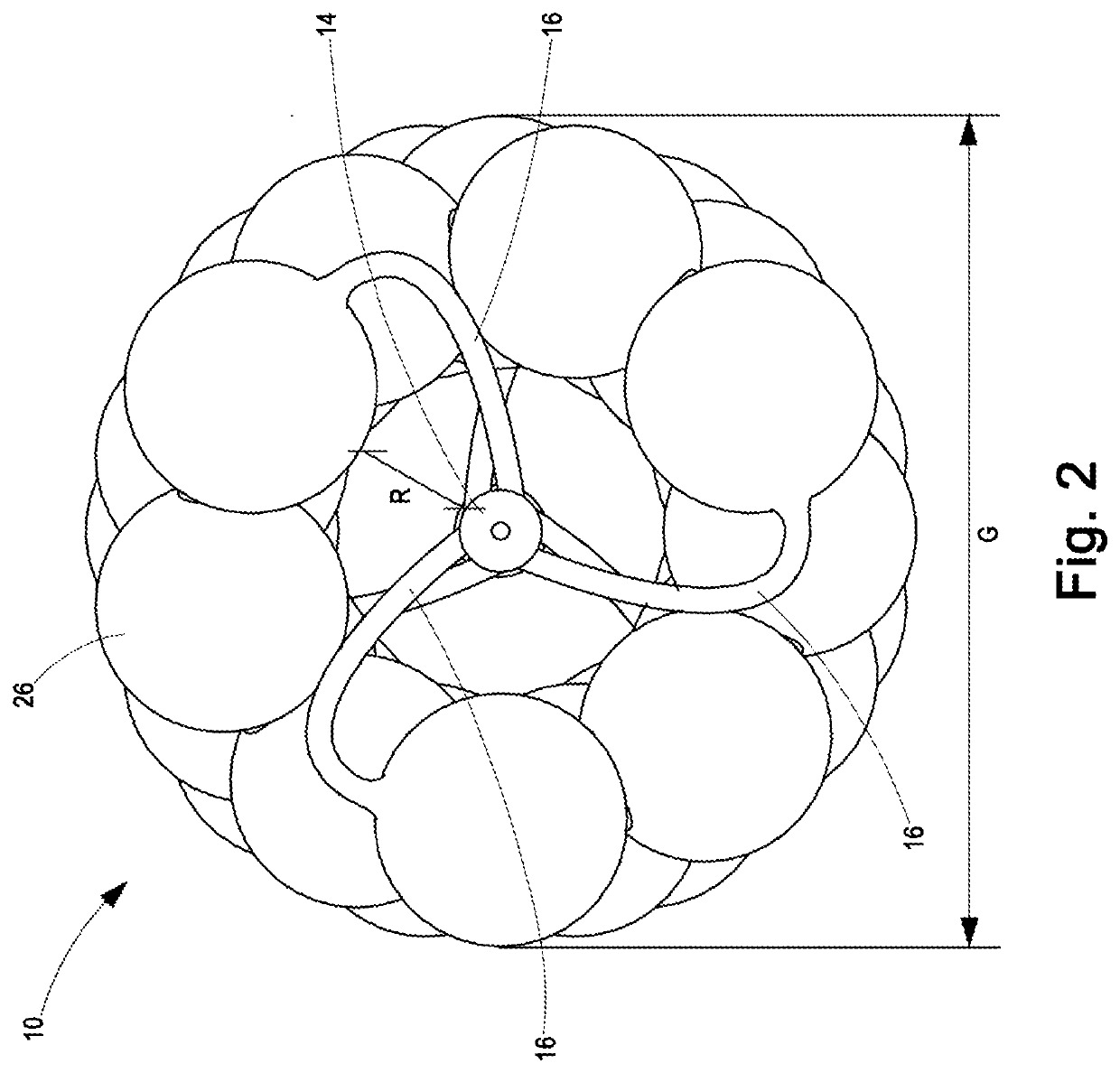
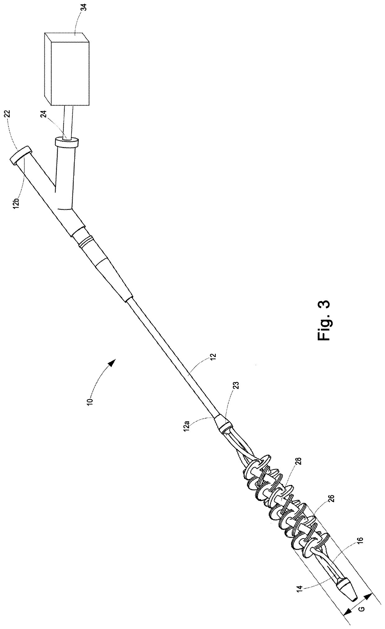
[0056]With reference to FIGS. 1 to 7 of the drawings, a dilatation device 10 according to a preferred embodiment of the invention is provided for dilating vessels and stents. The dilatation device 10 includes a locating tube 12, a support 14 and three inflatable tubes 16 would helically about the support 14.

[0057]The locating tube 12 is an elongate hollow tube between 900 mm and 1200 mm in axial length, which defines co-axial bores—a central bore 18; and an outer bore 20—that extend between the first and second axial ends 12a and 12b, respectively, of the locating tube 12. However, the outer bore 20 terminates prior to the second axial end 12b of the locating tube 12. The locating tube 12 is sufficiently flexible, in use, to permit the locating tube 12 to be inserted into and pass along a non-linear artery, and sufficiently strong to resist hoop stresses resulting from pressurisation of fluid within the locating tube 12 bores 18 and 20. Preferably, the locating tube 12 is made of a ...


PUM


Abstract

A dilatation device 10 includes a support 14 and at least one inflatable tube 16. The inflatable tube is wound helically around the support and also defines a series of inflatable zones 26 along its length, with successive inflatable zones spaced by an intermediate zone 28 that is more resistive to radial expansion than the inflatable zones. The inflatable tube further defines a fluid inlet 22, 24 for: introducing fluid to inflate the inflatable zones; and extracting fluid from the inflatable tube to deflate it, with each inflatable zone being in fluid communication with its successive inflatable zones via the intermediate zones. The axial critical buckling load of the inflatable zones is less than the radial critical buckling load of the inflatable zones, to cause the inflatable zones to concertina axially when the inflatable tube is depressurized, thereby causing the intermediate zones to displace towards each other.

Description

BACKGROUND[0001]The present invention relates to a dilatation device. More particularly, the present invention relates to a dilatation device including an axially collapsible helical beaded balloon.[0002]Various Inflatable Dilatation Devices are Known. For Instance:[0003]US2003 / 0176758 “Catheter for radiation therapy”, US2009 / 0281612 “Balloon catheter stent delivery system with ridges”, US2012 / 0059401 “Device and method for compartmental vessel treatment”, US2013 / 0116655 “Balloon assemblies having controllably variable topographies” and US2013 / 0218181 “Constraining structure with non-linear axial struts” describe dilators including an inflatable tube within a rigid tubular body, wherein inflation of the inflatable tube causes portions of the inflatable tube to protrude radially through apertures defined by the rigid tubular body.[0004]US2002 / 0120321 “Stent retention mechanism”, US2014 / 0066960 “System and method for treating biological vessels”, US2015 / 0133988 “Flexible high-pressure...

Claims


Application Information

Patent Timeline
Patent Type & Authority Applications(United States)
IPC IPC(8): A61M25/10A61M29/02
CPCA61F2/958A61M2025/1072A61M25/1011A61M25/1002A61M2025/1084A61M2025/1061A61M29/02A61M25/104
Inventor ZILLA, PETER PAULBEZUIDENHOUT, DEONMUDGE, EDWARD CHARLES TEDDY
Owner TEVAR PTY LTD
Why Eureka
Try Eureka