Fan noise-lowering structure

Active Publication Date: 2019-11-21
ASIA VITAL COMPONENTS SHENZHEN CO LTD
View PDF4 Cites 3 Cited by
  • Summary
  • Abstract
  • Description
  • Claims
  • Application Information

AI Technical Summary

Benefits of technology

[0012]According to the above arrangement of the present invention, a jet structure is disposed on the fan frame main body itself to guid

Problems solved by technology

Fan noise is always one of the problems to improve in the fan field.
This cannot be

Method used


Image

  • Fan noise-lowering structure
  • Fan noise-lowering structure
  • Fan noise-lowering structure

Examples


Example

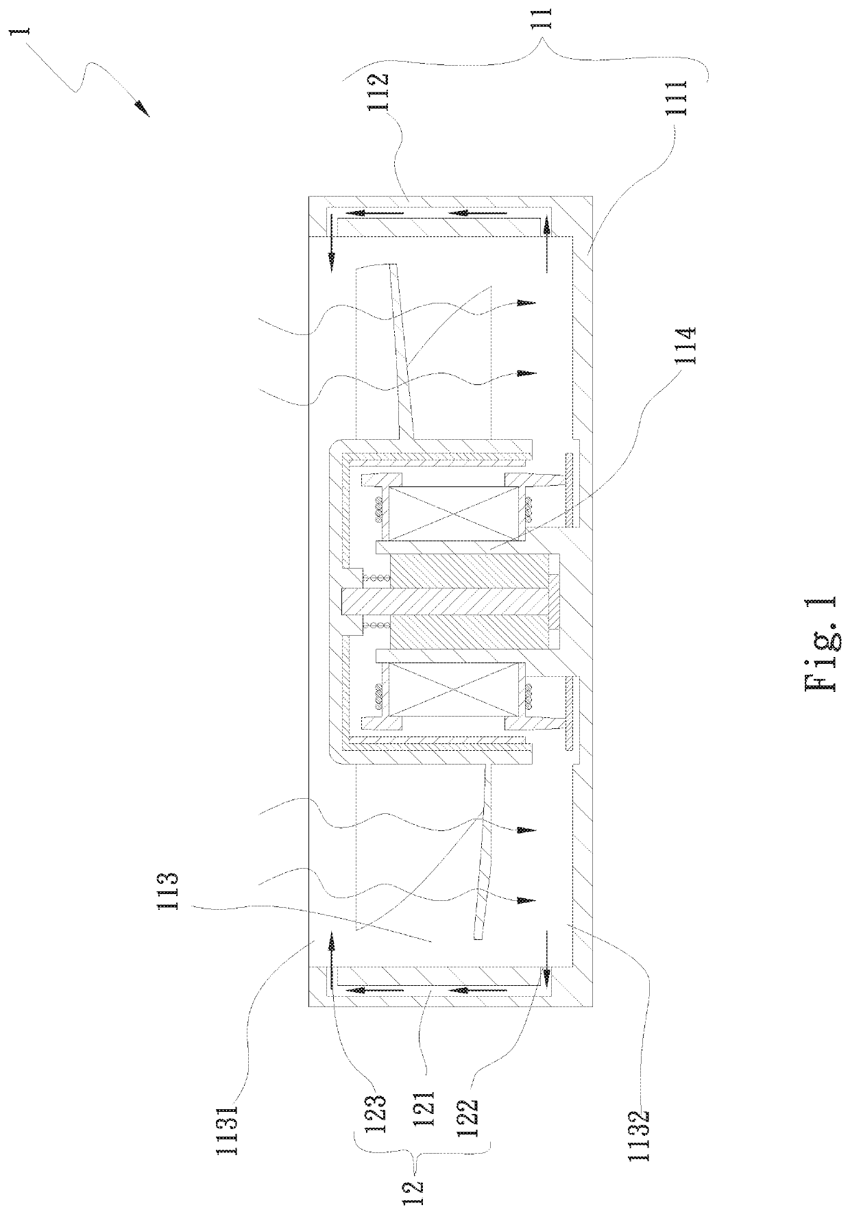
[0017]Please refer to FIG. 1, which is a sectional view of a first embodiment of the fan noise-lowering structure of the present invention. According to the first embodiment, the fan noise-lowering structure 1 of the present invention includes a fan frame main body 11 and a connection section 12.

[0018]The fan frame main body 11 has a bottom side 111 and a frame peripheral wall 112. The frame peripheral wall 112 is perpendicularly annularly disposed on outer rim of the bottom side 111. The inner rim of the frame peripheral wall 112 defines an airflow passage 113. Two ends of the airflow passage 113 respectively have an inlet 1131 and an outlet 1132. The outlet 1132 of the airflow passage 113 is disposed in adjacency to the bottom side 111. The inlet 1131 is disposed at one end of the airflow passage 113 opposite to the outlet 1132.

[0019]The connection section 12 is disposed in the frame peripheral wall 112. The connection section 12 has a middle passage 121. Two ends of the middle pa...

Example

[0021]Please now refer to FIG. 2, which is a sectional view of a second embodiment of the fan noise-lowering structure of the present invention. According to the second embodiment, the fan noise-lowering structure 2 of the present invention includes a first fan frame main body 21, a second fan frame main body 22 and a connection section 23.

[0022]The first fan frame main body 21 has a first bottom side 211 and a first frame peripheral wall 212. The first frame peripheral wall 212 is perpendicularly annularly disposed on outer rim of the first bottom side 211. The inner rim of the first frame peripheral wall 212 defines a first airflow passage 213. Two ends of the first airflow passage 213 respectively have a first inlet 2131 and a first outlet 2132.

[0023]The second fan frame main body 22 has a second bottom side 221 and a second frame peripheral wall 222. The second frame peripheral wall 222 is perpendicularly annularly disposed on outer rim of the second bottom side 221. The inner r...

Example

[0029]Please now refer to FIG. 3, which is a sectional view of a third embodiment of the fan noise-lowering structure of the present invention. According to the third embodiment, the fan noise-lowering structure 3 of the present invention includes a first fan frame main body 31, a second fan frame main body 32 and a connection section 33.

[0030]The third embodiment is partially identical to the second embodiment in structure and thus will not be redundantly described hereinafter. The third embodiment is different from the second embodiment in that the first and second fan frame main bodies 31, 32 are horizontally arranged in parallel to form a parallel fan. The first fan frame main body 31 has a first inlet 311 and a first outlet 312. The second fan frame main body 32 has a second inlet 321 and a second outlet 322. The first and second inlets 311, 321 are arranged in parallel. The middle passage 331 of the connection section 33 serves to guide the higher-pressure airflow of the secon...


PUM


Abstract

A fan noise-lowering structure includes a fan frame main body and a connection section. The fan frame main body has a bottom side and a frame peripheral wall. The frame peripheral wall is perpendicularly annularly disposed on the outer rim of the bottom side. The inner rim of the frame peripheral wall defines an airflow passage. Two ends of the airflow passage respectively have an inlet and an outlet. The connection section is disposed in the frame peripheral wall. Two ends of the connection section are connected with the frame peripheral wall. The two ends of the middle passage are an inlet end and an outlet end in communication with the airflow passage. The connection section serves to guide the high-pressure air of the outlet to jet toward the inlet so as to achieve multiple noise-lowering effects.

Description

BACKGROUND OF THE INVENTION1. Field of the Invention[0001]The present invention relates generally to a fan noise-lowering structure, and more particularly to a fan noise-lowering structure, which is able to guide the high-pressure airflow generated at the outlet of the fan to jet toward the inlet so as to achieve multiple noise-lowering effects.2. Description of the Related Art[0002]Fan noise is always one of the problems to improve in the fan field. Conventionally, a circuit is used to control the rotational speed of the fan or the fan structure is changed so as to solve the fan noise problem. U.S. Pat. No. 6,244,817 discloses a conventional method for solving the fan noise problem, in which a jet is disposed on the dynamic blade or static blade frame wall to restrain vortex. However, it is necessary to additionally externally connect the fan to a jet source. This cannot be done in a limited space. Also, the additional jet source leads to increase of cost.[0003]It is therefore trie...

Claims


Application Information

Patent Timeline
IPC IPC(8): F01D5/14F01D25/24
CPCF01D25/24F05D2260/96F01D5/141G06F1/20F04D25/0613F04D19/002F04D19/007F04D25/166F04D29/682F04D29/684
Inventor LIU, WEN-HAO
Owner ASIA VITAL COMPONENTS SHENZHEN CO LTD
Why Eureka
Try Eureka