
Serial Fan Device

Inactive Publication Date: 2015-01-22
SUNONWEALTH ELECTRIC MACHINE IND
View PDF7 Cites 9 Cited by
  • Summary
  • Abstract
  • Description
  • Claims
  • Application Information

AI Technical Summary

Benefits of technology

The objective of this patent is to create a fan that reduces vibrations and noise, and keeps the electronic system stable and operational. It does this by designing a fan that breaks the route of vibration transmission efficiently and dampens the vibrations caused by the fan's operation.

Problems solved by technology

Unfortunately, since there is vibration in the operation of a fan usually, the degree of the vibration of a serial fan device formed by plural fans can be much more serious than that of a single fan.
When the serial fan device is applied in an electronic system, such as a computer server, this kind of serious vibration not only induces noises, but also lowers the operational stability of the electronic system as well as accelerates the deterioration of the circuit joints inside the electronic system, and thus shortens the lifetime of this electronic system.
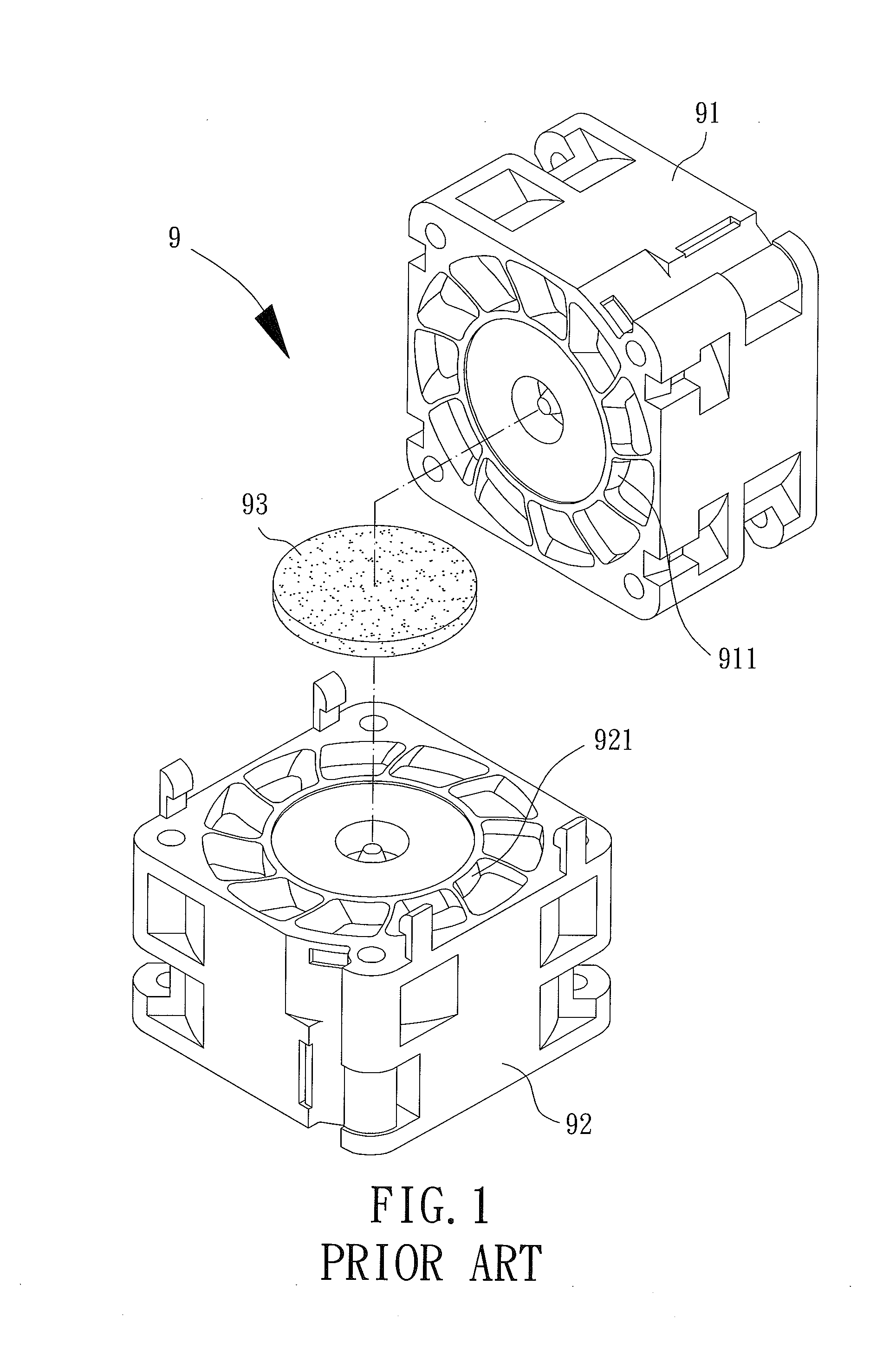
As a result, the damping performance provided by the damping member 93 against the resonance and noise is quite limited, and thus the remaining vibration can still lower the operational stability of an electronic system, induce noises, and shorten the lifetime of this electronic system when the serial fan device 9 is installed in this electronic system and operated.
Moreover, the said remaining vibration may also cause a fault or failure in reading operation of a hard disk in the electronic system.

Method used


Image

  • Serial Fan Device
  • Serial Fan Device
  • Serial Fan Device

Examples


Embodiment Construction

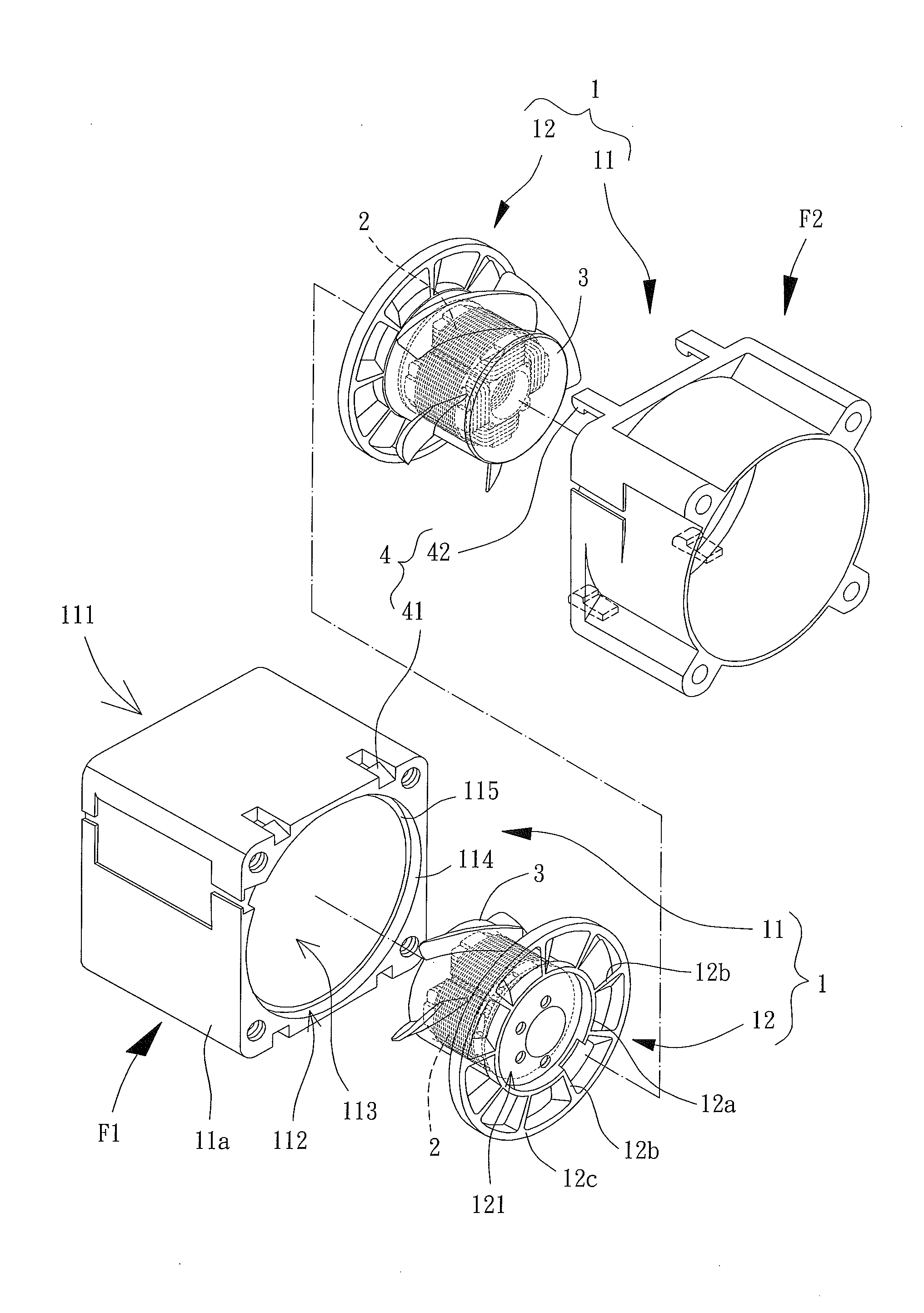
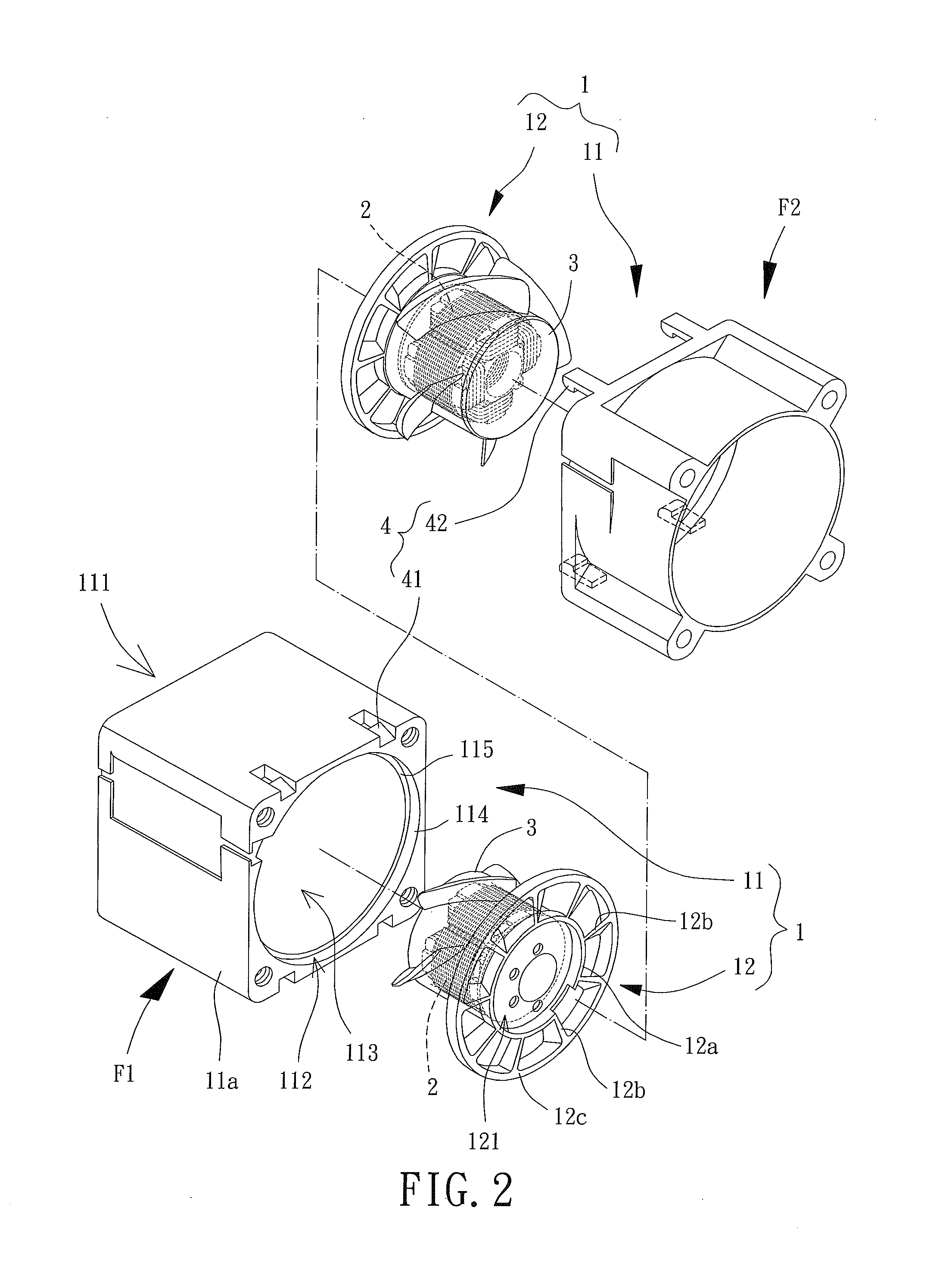
[0043]Referring to FIGS. 2 and 3, a first embodiment of a serial fan device of the present invention is shown, which includes a first fan F1 and a second fan F2, wherein axial directions of the first and second fans F1, F2 are in alignment and these two fans F1, F2 are linked serially.

[0044]The first fan F1 includes a housing 1, a driving member 2 and a fan wheel 3. The housing 1 includes an outer frame 11 and a base 12. The outer frame 11 has two openings 111, 112 and a guiding channel 113 linking these two openings 111, 112, wherein any one of the openings 111, 112 serves as an air inlet and the other one serves as an air outlet, such as the opening 111 serves as the air inlet while the opening 112 serves as the air outlet, and vice versa. The outer frame 11 has a positioning rim 114 with an axial shoulder 115 forming a supporting surface facing the opening 112. Therefore, the base 12 can be inserted in and surrounded by the positioning rim 114 and abut against the supporting surf...


PUM


Abstract

a serial fan device including two fans linked serially is provided. Each of the two fans has a housing, a driving member and a fan wheel, the housing has an outer frame and a base, the outer frame has two openings and a guiding channel linking the two openings, the driving member is disposed on the base, and the fan wheel is rotatably coupled with the driving member. At least one of the two fans has a positioning rim on the outer frame for the base to couple therewith, and a radial buffer gap is formed between an outer periphery of the base and an inner periphery of the positioning rim. Accordingly, the radial buffer gap can largely reduce the vibration transmitted from the base to the outer frame.

Description

BACKGROUND OF THE INVENTION[0001]1. Field of the Invention[0002]The present invention generally relates to a serial fan device and, more particularly, it relates to a serial fan device formed by a plurality of fans serially combined.[0003]2. Description of the Related Art[0004]A conventional serial fan device is usually formed by a plurality of series-connected fans so as to provide improved wind volume and enhanced cooling effect relative to a single fan. Unfortunately, since there is vibration in the operation of a fan usually, the degree of the vibration of a serial fan device formed by plural fans can be much more serious than that of a single fan. When the serial fan device is applied in an electronic system, such as a computer server, this kind of serious vibration not only induces noises, but also lowers the operational stability of the electronic system as well as accelerates the deterioration of the circuit joints inside the electronic system, and thus shortens the lifetime...

Claims


Application Information

Patent Timeline
IPC IPC(8): F04D19/00
CPCF04D19/007F04D29/668F04D29/646F04D25/166F04D29/663
Inventor LI, MING-TSUNGCHANG, FENG-MING
Owner SUNONWEALTH ELECTRIC MACHINE IND
Learn More