Mobile CNC machining machine

a machining machine and mobile technology, applied in the field of mobile cnc machine tools, can solve the problems of high mechanical and/or thermal load on the rotor of steam turbines of power plants, high cost, long downtime of power plants, etc., and achieve the effect of compact structure of cnc machine tools and reducing vibrations

Inactive Publication Date: 2019-12-19
SIEMENS ENERGY GLOBAL GMBH & CO KG
View PDF0 Cites 0 Cited by
  • Summary
  • Abstract
  • Description
  • Claims
  • Application Information

AI Technical Summary

Benefits of technology

[0007]An aspect relates to a mobile CNC machine tool of the type mentioned at the beginning which is characterized in that the tool module is guided on a convex guide in the shape of an arc of a circle arranged on the stand, and can be displaced about a C axis which extends parallel to the X axis, in that the Z axis intersects the C axis, and in that the Y axis extends tangentially to a circular path which has the C axis as a center point. In this way, a new machine tool design is obtained which is distinguished from the known machine tool designs in particular in that there is no headstock or tailstock and hence the rotor to be machined is not held so that it can be driven in rotation about a C axis of the machine tool. Instead, in the CNC machine tool according to embodiments of the invention, the tool module which can be displaced along the X axis, the Y axis, and the Z axis can be positioned about the C axis along the convex guide in the shape of an arc of a circle arranged on the stand. This means that in particular the bottom plate and the machine bed can be designed so that they are very small, as a result of which a relatively very low dead weight of the CNC machine tool according to embodiments of the invention can be obtained, which has an influence in particular on the transportability and the associated costs. Moreover, the structure of the CNC machine tool according to embodiments of the invention can be very compact, which entails low acquisition costs.
[0008]According to embodiments of the present invention, the bottom plate has a plurality of leveling devices which are designed for orienting the bottom plate relative to a subsurface. Accordingly, the CNC machine tool according to embodiments of the invention can be set up without any problem on a wide range of subsurfaces and oriented relative to the subsurface and / or the workpiece to be machined.
[0009]A baseplate is fastened removably to the bottom plate using screws and centering pins, the baseplate being provided on its upper surface with linear guides for the displacement of the stand along the X axis. The removable arrangement is conducive to a modular structure of the CNC machine tool and to the associated good transportability. The centering is expedient for ensuring that the orientation of the CNC machine tool is not lost in the event of it being repositioned multiple times.
[0011]A working platform, in particular one with an integrated switch cabinet, is advantageously fastened on the intermediate plate. In this way, a very compact structure of the CNC machine tool according to embodiments of the invention is obtained.
[0012]According to embodiments of the present invention, the stand is designed as a cast construction, which is advantageous for reducing vibrations.

Problems solved by technology

Rotors of steam turbines of a power plant are subject to high mechanical and / or thermal loads during operation.
The transporting is, however, very time-intensive and entails a long downtime for the power plant and correspondingly high costs.
The CNC machine tool described in WO 2013 / 178377 A1 is, however, very bulky and has a high dead weight, which is a disadvantage in terms of acquisition costs and transportation.
Moreover, it takes up a very large amount of space which is not available in all power plants.

Method used


Image

  • Mobile CNC machining machine
  • Mobile CNC machining machine
  • Mobile CNC machining machine

Examples


Embodiment Construction

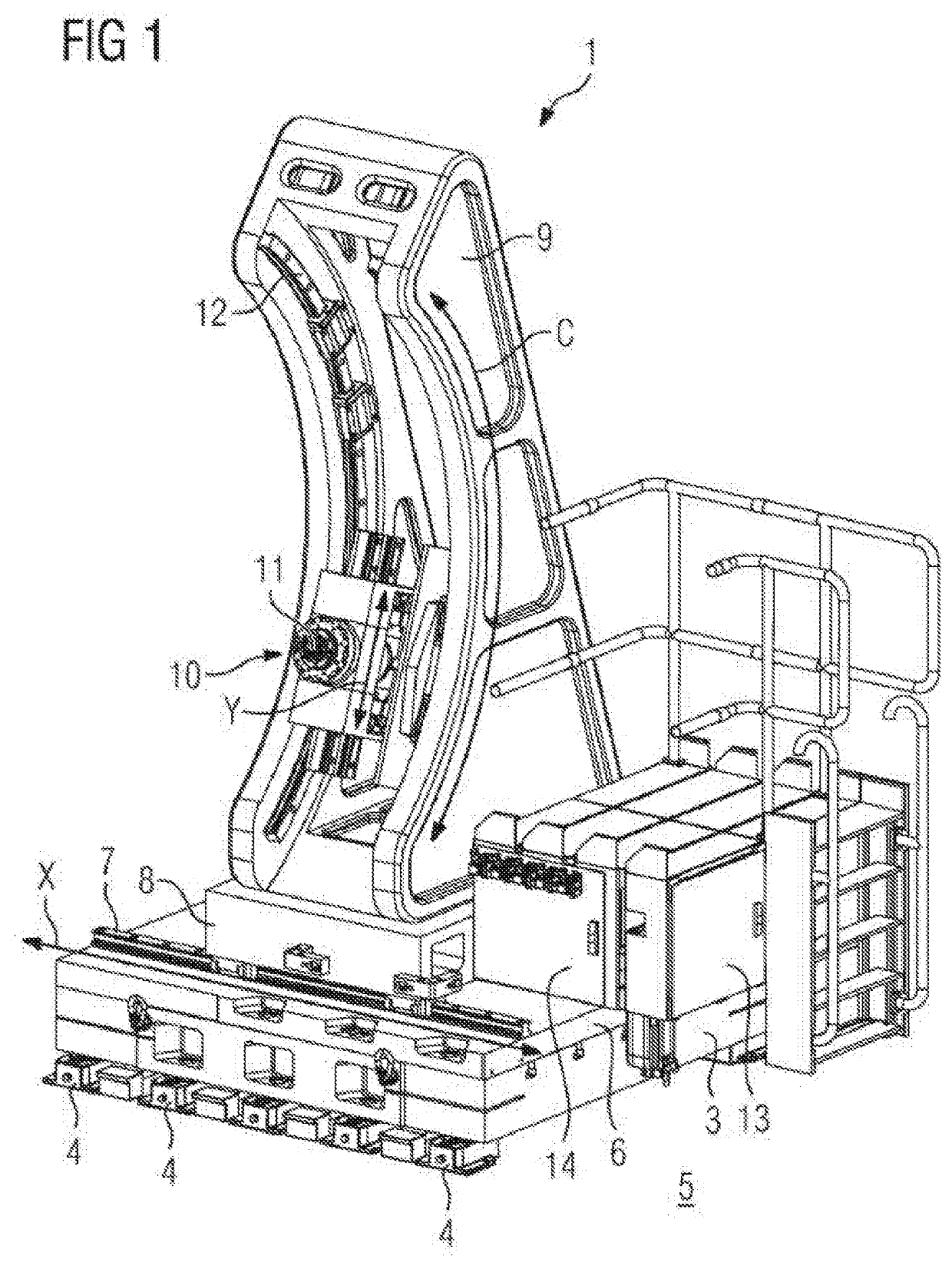
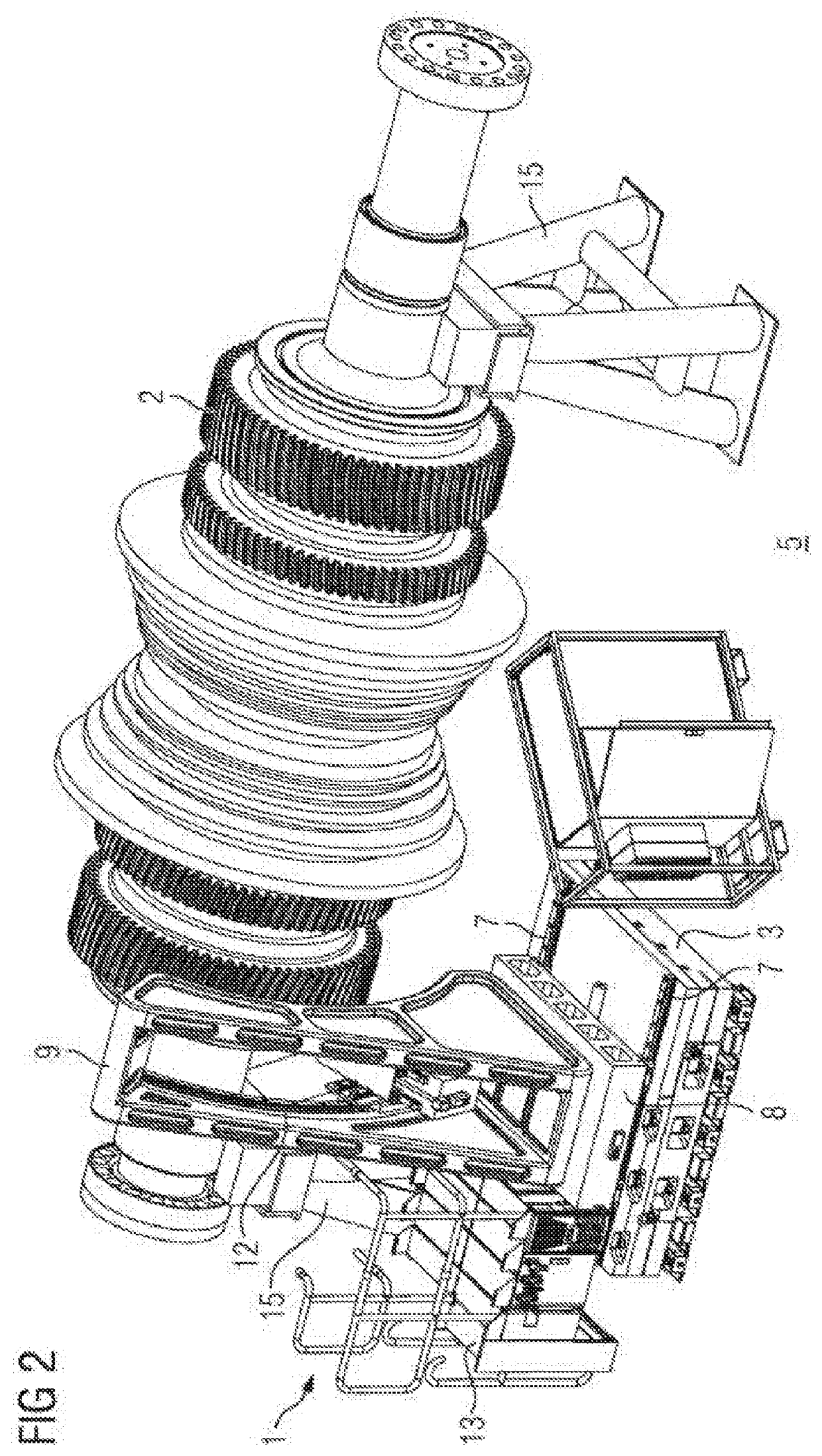
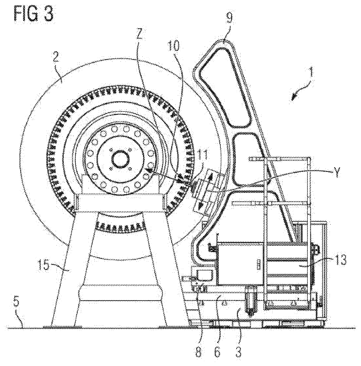
[0021]The mobile CNC machine tool 1 serves to machine a rotor 2 of a continuous-flow machine, such as, for example, a rotor of a steam turbine. It has a modular structure, the size of the modules being chosen such that, in the disassembled state, the CNC machine tool can be transported in conventional freight containers and is accordingly mobile. The CNC machine tool 1 comprises a bottom plate 3 with a plurality of leveling devices 4 which are designed for orienting the bottom plate 3 relative to a subsurface 5. A baseplate 6, which is provided on its top side with linear guides 7 extending in the direction of an X axis of the CNC machine tool 1, is fastened removably to the bottom plate 3 using screws and centering pins (not shown in detail). An intermediate plate 8, on which a stand 9 is fastened, is guided on the linear guides 7, wherein the intermediate plate 8 is fastened removably using fastening screws and centering pins (likewise not shown in detail). A tool module 10 is he...


PUM

PropertyMeasurementUnit
displacementaaaaaaaaaa
angleaaaaaaaaaa
dead weightaaaaaaaaaa

Abstract

Provided is a mobile CNC machining machine which is designed to machine a rotor of a turbomachine, wherein the turbomachine is a rotor of a steam turbine, including an x-axis, a y-axis and a z-axis which are arranged perpendicular to one another, a baseplate, a stator which is arranged on the baseplate and is movable relative to the baseplate along the x-axis, and a tool module which is held on the stator and is movable along the y-axis and along the z-axis and is designed to accommodate a machining tool wherein, guided along a circular-arc-shaped convex guide disposed on the stator, the tool module is movable about a c-axis which extends parallel to the x-axis; in that the z-axis intersects the c-axis; and in that the y-axis extends tangentially to a circular path, of which the c-axis is the center point.

Description

CROSS-REFERENCE TO RELATED APPLICATIONS[0001]This application claims priority to PCT Application No. PCT / EP2017 / 056090, having a filing date of Mar. 15, 2017, which is based on German Application No. 10 2017 201 497.0, having a filing date of Jan. 31, 2017, the entire contents both of which are hereby incorporated by reference.FIELD OF TECHNOLOGY[0002]The following relates to a mobile CNC machine tool which is designed to machine a rotor of a continuous-flow machine, in particular to machine a rotor of a steam turbine, comprising an X axis, a Y axis, and a Z axis which are each arranged at right angles to one another, a bottom plate, a stand arranged on the bottom plate and capable of being displaced relative to the latter along the X axis, and a tool module which is held on the stand so that it can be displaced along the Y axis and along the Z axis and is designed for receiving a machining tool.BACKGROUND[0003]Rotors of steam turbines of a power plant are subject to high mechanical...

Claims


Application Information

Patent Timeline
Patent Type & Authority Applications(United States)
IPC IPC(8): B23Q1/00B23Q1/01
CPCE02D27/44B23Q37/005B23Q1/0054B23Q1/015B23Q17/007B23Q2210/006Y10T409/307672Y10T409/308232B23C1/12B23C3/02B23C2215/56Y10T409/303752
Inventor POTYKA, SEBASTIANSELLMANN, STEFANVOGT, FELIXLÜPFERT, JANNIK
Owner SIEMENS ENERGY GLOBAL GMBH & CO KG
Why Eureka
Try Eureka