Passive Virtual Synchronous Machine with Bounded Frequency and Virtual Flux

a virtual synchronous machine and passive technology, applied in the direction of electric generator control, dynamo-electric converter control, dynamo-electric gear control, etc., can solve the problems of imposing unprecedented challenges on the frequency stability of future power systems, unsuitable conventional control of current of power electronic converters, and changing the landscape of power systems. to achieve the effect of facilitating understanding

Active Publication Date: 2019-12-19
ZHONG QINGCHANG
View PDF0 Cites 7 Cited by
  • Summary
  • Abstract
  • Description
  • Claims
  • Application Information

AI Technical Summary

Benefits of technology

[0005]The following summary is provided to facilitate an understanding of some of the innovative features unique to the disclosed embodiments and is not intended to be a full d...

Problems solved by technology

But now, the landscape of power systems is rapidly changing.
Hence, the number of active players to take part in frequency control in the future could easily reach millions, which imposes unprecedented challenges to the frequency stability of future power systems.
The fundamental challenge behind t...

Method used

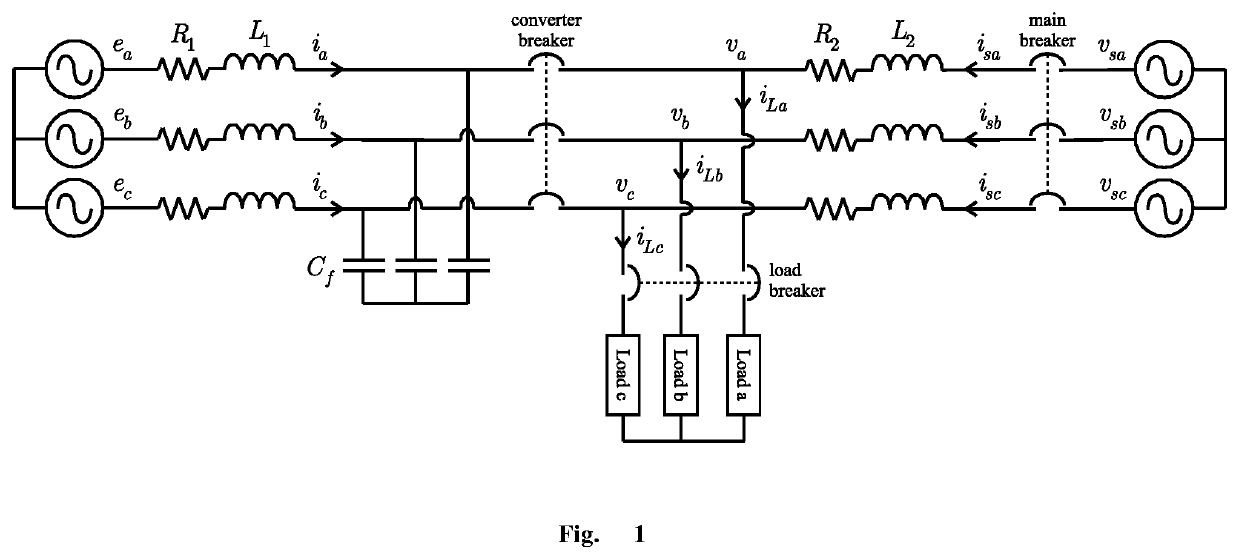
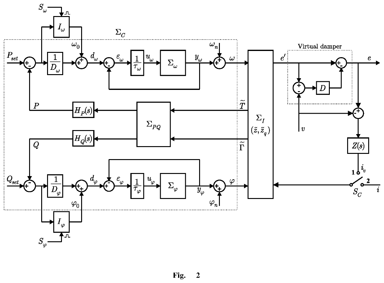
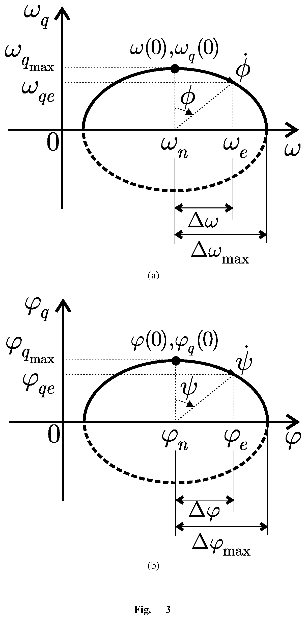

Image

  • Passive Virtual Synchronous Machine with Bounded Frequency and Virtual Flux
  • Passive Virtual Synchronous Machine with Bounded Frequency and Virtual Flux
  • Passive Virtual Synchronous Machine with Bounded Frequency and Virtual Flux

Examples


Embodiment Construction

[0013]The particular values and configurations discussed in these non-limiting examples can be varied and are cited merely to illustrate at least one embodiment and are not intended to limit the scope thereof.

[0014]The embodiments will now be described more fully hereinafter with reference to the accompanying drawings, in which illustrative embodiments of the invention are shown. The embodiments disclosed herein can be embodied in many different forms and should not be construed as limited to the embodiments set forth herein; rather, these embodiments are provided so that this disclosure will be thorough and complete, and will fully convey the scope of the invention to those skilled in the art.

[0015]The terminology used herein is for the purpose of describing particular embodiments only and is not intended to be limiting of the invention. As used herein, the singular forms “a,”“an,” and “the” are intended to include the plural forms as well, unless the context clearly indicates othe...


PUM


Abstract

This invention discloses a controller and method to operate a power electronic converter as a virtual synchronous machine with bounded frequency and virtual flux. The converter can be operated in the grid-connected mode or the is landed mode to take part in the regulation of the frequency and the voltage. The controller consists of (1) a real power-frequency channel to regulate the frequency, (2) a reactive power-flux channel to regulate the virtual flux (equivalently, the voltage amplitude), (3) an interconnection block that takes the frequency, the virtual flux, and an input current to generate a voltage, a signal {tilde over (T)}, and a signal {tilde over (Γ)} that are fed through a block and two passive filters to generate the negative real power feedback signal for the real power-frequency channel and the negative reactive power feedback signal for the reactive power-flux channel, respectively, (4) a virtual damper to generate an output voltage as the control signal for the power electronic converter according to the voltage generated by the interconnection block and a first measured voltage, and (5) a virtual impedance to generate a virtual current according to the difference of the output voltage and a second measured voltage. The controller also includes auxiliary blocks to achieve self-synchronization without measuring or estimating the grid frequency and the regulation of real power and reactive power to given reference values without static errors.

Description

CROSS-REFERENCE TO RELATED APPLICATIONS[0001]This nonprovisional patent application claims the benefit of and priority under 35 U.S. Code 119 (b) to U.K. Patent Application No. GB1809724.6 filed on Jun. 14, 2018, entitled “Passive Virtual Synchronous Machine with Bounded Frequency and Virtual Flux”, the contents of which are all hereby incorporated by reference herein in its entirety.TECHNICAL FIELD[0002]This invention is concerned with the control and operation of power electronic converters. Possible application fields include renewable energy, such as wind, solar and wave energy, electrical vehicles, energy storage systems, aircraft power systems, different types of loads that require power electronic converters, data centres and so on.BACKGROUND[0003]Power systems are going through a paradigm change. At the moment, the frequency of a power system is controlled by regulating a small number of large synchronous generators and most loads do not take part in the frequency control of...

Claims


Application Information

Patent Timeline
IPC IPC(8): H02P21/00G06F17/50
CPCH02P21/0003G06F2217/16G06F17/5009H02J3/48H02J3/50H02J3/38H02M7/48H02M7/521H02M1/0003H02M1/0025G06F30/20G06F2111/10
Inventor ZHONG, QINGCHANG
Owner ZHONG QINGCHANG
Why Eureka
Try Eureka