Innovative Energy Generating Photovoltaic Awning

Active Publication Date: 2019-12-19
EVOLUSUN INC
View PDF8 Cites 17 Cited by
  • Summary
  • Abstract
  • Description
  • Claims
  • Application Information

AI Technical Summary

Benefits of technology

[0021]On the other hand, in embodiments where the panels are detached from one another, when the lead arm is fully extended the solar panels will hang from the lead wire separated by the length of the attachment between the panels. In that case, an additional mechanism is needed to tilt the panel sideways from a vertical position to a substantially horizontal position so that the panels can form a continuous covering at the top of the awning, with solar cells facing the sun and providing shade below.
[0022]The tilt of the panels (e.g., hanging panels) can be ach

Problems solved by technology

The issue with this methodology is that all these solutions require the use of thin film solar cells in a roll-able fabric like form.
Such roll-able film solar panels either do not have high enough efficiencies (as in the case of amorphous silicon cells) or are very expensive (like III-V cells or CIGS).
Additionally, the rolling and un-rolling of the thin film solar cells lead to fatigue in the cells and has the potential to reduce its life span.
The issue with this approach is that energy generating surface area in these embodiment

Method used


Image

  • Innovative Energy Generating Photovoltaic Awning
  • Innovative Energy Generating Photovoltaic Awning
  • Innovative Energy Generating Photovoltaic Awning

Examples


Embodiment Construction

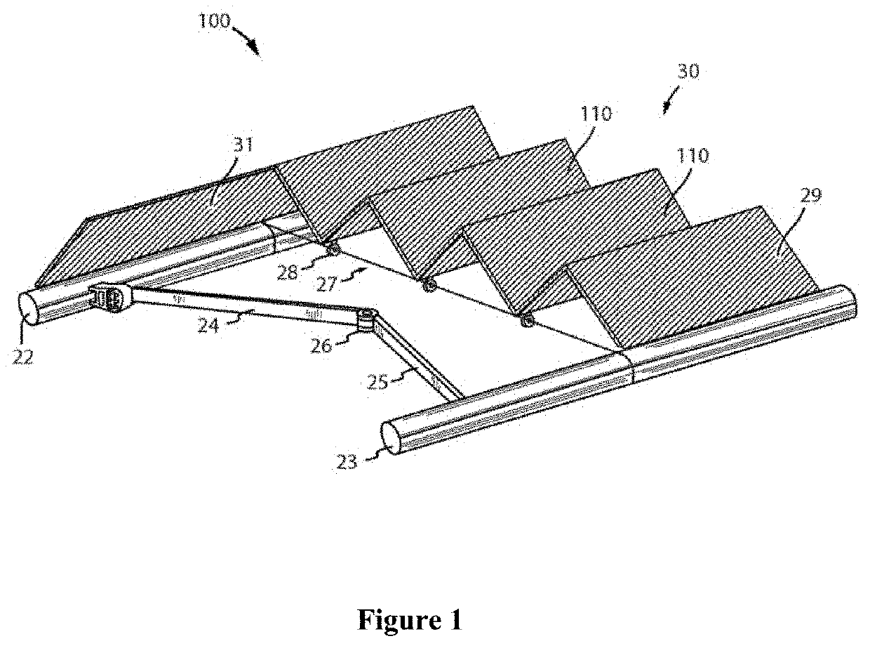
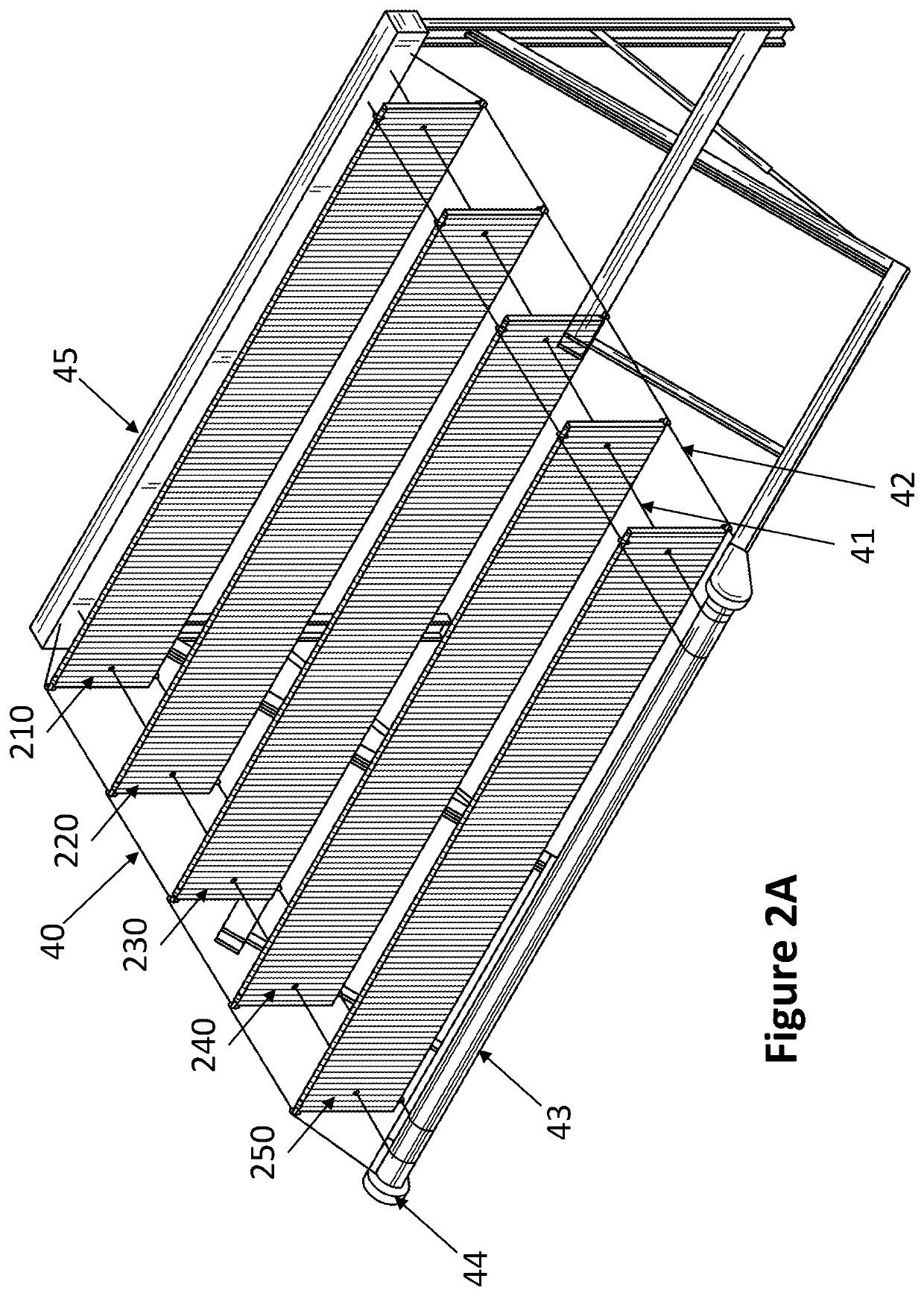
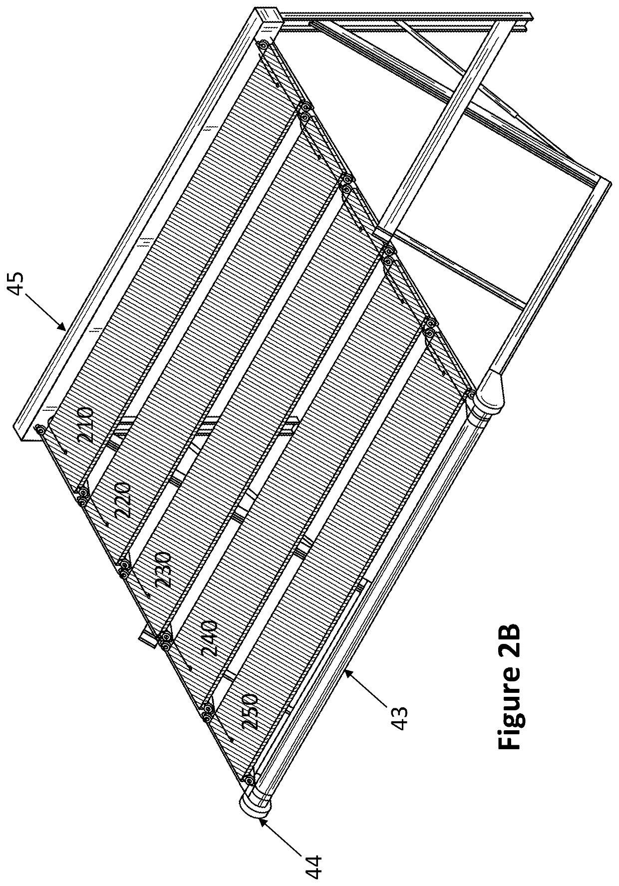
[0029]The present invention provides a unique, smart and commercially deployable, expandable solar awning and canopy systems.

[0030]Awnings or canopies are contemplated that have a base and a leading arm. The base is typically coupled to a surface, for example the eave or roof of a structure or the side of a vehicle (e.g., RV). A first panel is coupled to the base of the awning and a second panel is coupled to the first panel and the leading arm of the awning. It is contemplated that the panel can be made of polymers, glass, wood, metal, or combinations or composites thereof, and can further incorporate functional elements, such as lights, sensors, heaters, acoustic devices, displays, or photovoltaic cells. In preferred embodiments, the panels are at least partly photovoltaic panels, preferably mostly photovoltaic panels, and more preferably predominantly photovoltaic panels. In some embodiments, photovoltaic cells make up at least 60% of a surface of the panels, preferably at least ...


PUM


Abstract

Apparatus, systems and methods are provided for solar awnings or canopies that include rigid solar modules, for example photovoltaic cells or panels. The awnings have solar modules or panels stacked together substantially vertically (e.g., each module is oriented vertically with respect to the next module). The solar modules in the stack are interconnected to each other, such that each solar module is connected electrically and mechanically to adjacent solar modules. The first solar module in the stack of modules is fixed to one end of the base of the awning. The base of the awning is typically mounted to a building, vehicle, mobile home, or other appropriate structure. The last solar module in the stack is attached to a lead arm of the awning. The lead arm moves back and forth (e.g., away and toward) from the base of the awning to enable the expansion or retraction of the awning.

Description

[0001]This application claims priority to copending U.S. provisional application No. 62 / 685,898 filed on Jun. 15, 2018, and copending U.S. provisional application No. 62 / 719,424 filed on Aug. 17, 2018. These and all other referenced extrinsic materials are incorporated herein by reference in their entirety. Where a definition or use of a term in a reference that is incorporated by reference is inconsistent or contrary to the definition of that term provided herein, the definition of that term provided herein is deemed to be controlling.FIELD OF THE INVENTION[0002]This invention is related to the field of expandable solar power generating systems. More specifically this application relates to a design for a novel photovoltaic awning system that can be expanded or retracted as needed.BACKGROUND[0003]The following description includes information that may be useful in understanding the present invention. It is not an admission that any of the information provided herein is prior art or...

Claims


Application Information

Patent Timeline
IPC IPC(8): H02S20/26H02S20/30H02S40/10
CPCH02S40/10B60R16/03H02S20/26B60Y2400/216E04F10/10H02S20/30B60P3/34H02S30/20B60R16/0307E04F10/08
Inventor RAGHUNATHAN, ROHINI
Owner EVOLUSUN INC
Why Eureka
Try Eureka