Liquid ejecting apparatus and liquid ejecting method

Active Publication Date: 2019-12-26
SEIKO EPSON CORP
View PDF7 Cites 1 Cited by
  • Summary
  • Abstract
  • Description
  • Claims
  • Application Information

AI Technical Summary

Benefits of technology

[0005]According to an aspect of the present disclosure, a liquid ejecting apparatus is provided. The liquid ejecting apparatus includes a nozzle that ejects liquid with a viscosity of 50 mPa·s or higher; a pressure chamber communicating with the nozzle; a pressure change portion that changes a pressure of the liquid in the pressure chamber; and a controller that controls the pressure change portion. The controller, by driving the pressure change portion, executes first control of decreasing the pressure of the liquid in the pressure chamber, hence pulling a center portion of a meniscus of the liquid in the nozzle toward the p

Problems solved by technology

Consequently, the inventors have determined that a phenomenon in which when the viscosity of the liquid increases, the resistance at the boundary between the inner wall surface of the nozzle and the liquid to be ejected increases and the loss of energy of

Method used


Image

  • Liquid ejecting apparatus and liquid ejecting method
  • Liquid ejecting apparatus and liquid ejecting method
  • Liquid ejecting apparatus and liquid ejecting method

Examples


first embodiment

A. First Embodiment

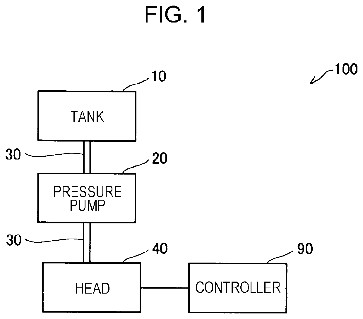
[0019]FIG. 1 is an explanatory view illustrating an outline configuration of a liquid ejecting apparatus 100 according to a first embodiment. The liquid ejecting apparatus 100 includes a tank 10, a pressure pump 20, a supply pipe 30, a head 40, and a controller 90.

[0020]The tank 10 houses liquid. The liquid in the tank 10 is compressed by the pressure pump 20 and is supplied to the head 40 through the supply pipe 30. The pressure pump 20 according to this embodiment is a metering pump capable of supplying liquid at a constant flow rate. As the metering pump, a gear pump with less pulsing may be employed. Alternatively, for example, a buffer tank for absorbing pulsing may be provided at a portion of the supply pipe 30, and one of various metering pumps of diaphragm type and plunger type may be used.

[0021]The liquid supplied to the head 40 through the supply pipe 30 is ejected by the head 40. The operation of the head 40 is controlled by the controller 90. The contr...


PUM


Abstract

A liquid-ejecting-apparatus includes a nozzle that ejects liquid with a viscosity of 50 mPa·s or higher; a pressure-chamber communicating with the nozzle; a pressure-change-portion that changes a pressure of the liquid in the pressure-chamber; and a controller that controls the pressure-change-portion. The controller executes first control of decreasing the pressure of the liquid in the pressure-chamber, hence pulling a center portion of a meniscus toward the pressure-chamber, and forming a liquid-membrane with the liquid at an inner-wall-surface of the nozzle; and second control of, in a state in which the liquid-membrane is formed at the inner-wall-surface of the nozzle, increasing the pressure of the liquid in the pressure-chamber, hence inverting a shape of the center portion of the meniscus to a protruding shape protruding toward an opening of the nozzle and forming a liquid-column, and further, ejecting the liquid-column so as not to contact the liquid membrane.

Description

[0001]The present application is based on, and claims priority from, JP Application Serial Number 2018-120388, filed Jun. 26, 2018, the disclosure of which is hereby incorporated by reference herein in its entirety.BACKGROUND1. Technical Field[0002]The present disclosure relates to a liquid ejecting apparatus and a liquid ejecting method.2. Related Art[0003]Various studies are being made to apply an ink jet technology to, for example, formation of electrodes, direct formation of various electrical components, formation of light emitting bodies and filters used for displays, and formation of microlenses. The increasing range of uses for the ink jet technology increases the variety of types of liquid to be ejected from nozzles. For example, JP-A-2010-110968 discloses a method of ejecting liquid with a high viscosity from a nozzle.[0004]With the liquid ejecting method of JP-A-2010-110968, the range of the viscosity of the liquid within which the liquid can be stably ejected from the no...

Claims


Application Information

Patent Timeline
IPC IPC(8): B41J2/045B41J2/18B41J2/175B41J2/14
CPCB41J2/17596B41J2/18B41J2/04581B41J2202/11B41J2/14274B41J2/04588B41J2/04501B41J2/14201B41J2002/14483B41J2202/12
Inventor SUGAI, KEIGO
Owner SEIKO EPSON CORP
Why Eureka
Try Eureka