

Method of fabricating ferroelectric liquid crystal display
- Summary
- Abstract
- Description
- Claims
- Application Information
AI Technical Summary
Benefits of technology
Problems solved by technology
Method used
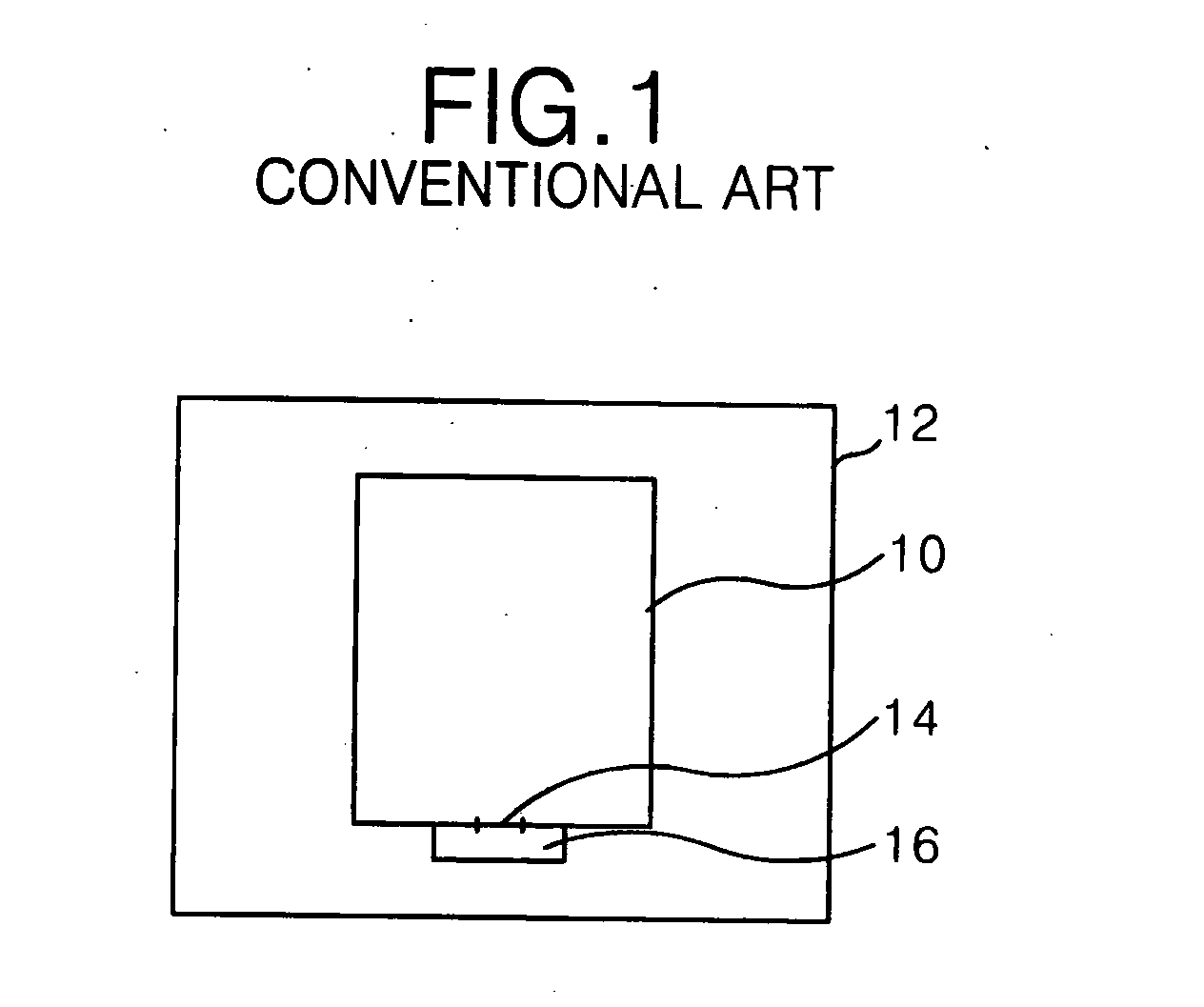
Image

Examples
first embodiment
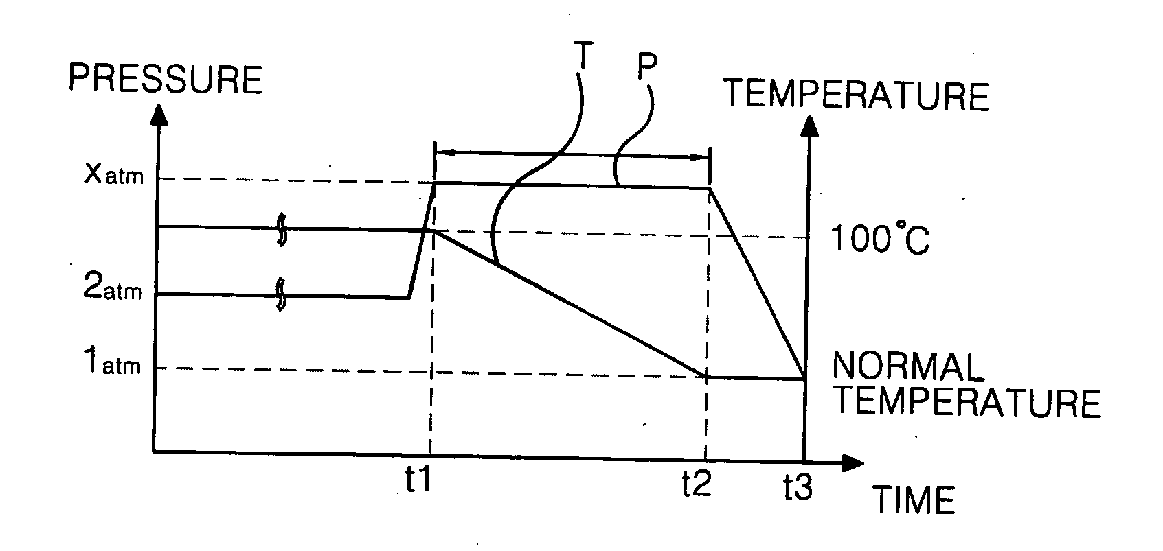
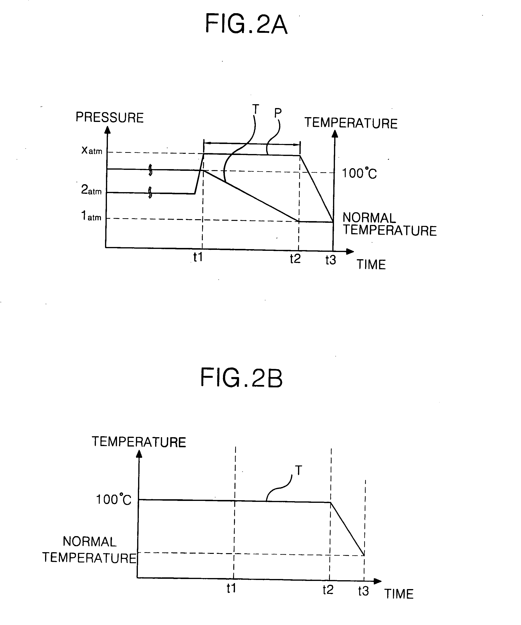
[0039]FIGS. 2A and 2B are graphic views illustrating the characteristics of change in the temperature and the pressure in a liquid crystal injection process of a method of fabricating a ferroelectric liquid crystal display according to the present invention. FIG. 2A is a graph illustrating the characteristics of the changes in the pressure P in a chamber 12 and the temperature T in a liquid crystal panel 10 according to time t in a liquid crystal injection device as shown in FIG. 1. FIG. 2B is a graph illustrating the characteristics of the change in temperature of a liquid crystal in a liquid crystal tray 16.
[0040] Firstly, an injection hole 14 of the liquid crystal panel 10 is contacted to the liquid crystal tray 16 in the chamber 12, which is in a vacuum state. Then gas is injected into the chamber 12 to increase and sustain the pressure in the chamber 12 to a first pressure, that is, a liquid crystal injection pressure (e.g., about 2 atmospheres (atm)). At the same time, the liq...
second embodiment
[0044]FIGS. 3A and 3B are graphic views illustrating the characteristics of change in the temperature and the pressure in a liquid crystal injection process of a method of fabricating a ferroelectric liquid crystal display according to the present invention. FIG. 3A is a graph illustrating the characteristics of the changes in the pressure P in a chamber 12 and the temperature T in a liquid crystal panel 10 according to time (t) in a liquid crystal injection device as shown in FIG. 1. FIG. 3B is a graph illustrating the characteristics of the change in the temperature of a liquid crystal in a liquid crystal tray 16.
[0045] Firstly, an injection hole 14 of the liquid crystal panel 10 is contacted to the liquid crystal tray 16 in the chamber 12, which is in a vacuum state. Then, gas is injected into the chamber 12 to increase and sustain the pressure in the chamber 12 to a first pressure, that is, a liquid crystal injection pressure (e.g., 2atm). At the same time, the liquid crystal pa...
third embodiment
[0049]FIGS. 4A and 4B are graphic views illustrating the characteristics of change in the temperature and the pressure in a liquid crystal injection process of a method of fabricating a ferroelectric liquid crystal display according to the present invention. FIG. 4A is a graph illustrating the characteristics of the changes in the pressure P in a chamber 12 and the temperature T in a liquid crystal panel 10 according to time (t) in a liquid crystal injection device as shown in FIG. 1. FIG. 4B is a graph illustrating the characteristics of the change in the temperature of a liquid crystal in a liquid crystal tray 16.
[0050] Firstly, an injection hole 14 of the liquid crystal panel 10 is contacted to the liquid crystal tray 16 in the chamber 12 which is in a vacuum state. Then, gas is injected into the chamber 12 to increase and sustain the pressure in the chamber 12 to a first pressure, that is, a liquid crystal injection pressure (e.g., about 2atm). At the same time, the liquid cryst...
PUM
 Abstract
Description
Claims
Application Information