Indicators for valves

Active Publication Date: 2022-11-22
CYRUS SHANK CORP
View PDF8 Cites 0 Cited by
  • Summary
  • Abstract
  • Description
  • Claims
  • Application Information

AI Technical Summary

Benefits of technology

[0004]The present invention relates broadly to indicators adapted to provide a visual indication of whether a pressure relief valve has been activated due to an over pressure situation in a system. In an embodiment, the indicator (also referred to as a pop indicator), includes a main body, a piston disposed in the main body, and one or more O-rings disposed around the piston. Initially, the piston is in a first position, wherein the piston is retracted into the body, thus providing an indication that an over pressurization event has not occurred. However, when an over pressure situation occurs, the increased pressure causes the piston to move in

Problems solved by technology

However, when an over pressure situation occurs, the increased pressure causes the piston to mov

Method used


Image

  • Indicators for valves
  • Indicators for valves
  • Indicators for valves

Examples


Example

[0028]While the present invention is susceptible of embodiments in many different forms, there is shown in the drawings, and will herein be described in detail, embodiments of the invention, including a preferred embodiment, with the understanding that the present disclosure is to be considered as an exemplification of the principles of the invention and is not intended to limit the broad aspect of the invention to embodiments illustrated. As used herein, the term “present invention” is not intended to limit the scope of the claimed invention and is instead a term used to discuss exemplary embodiments of the invention for explanatory purposes only.

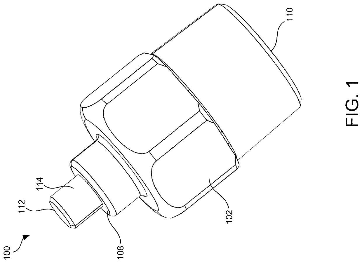
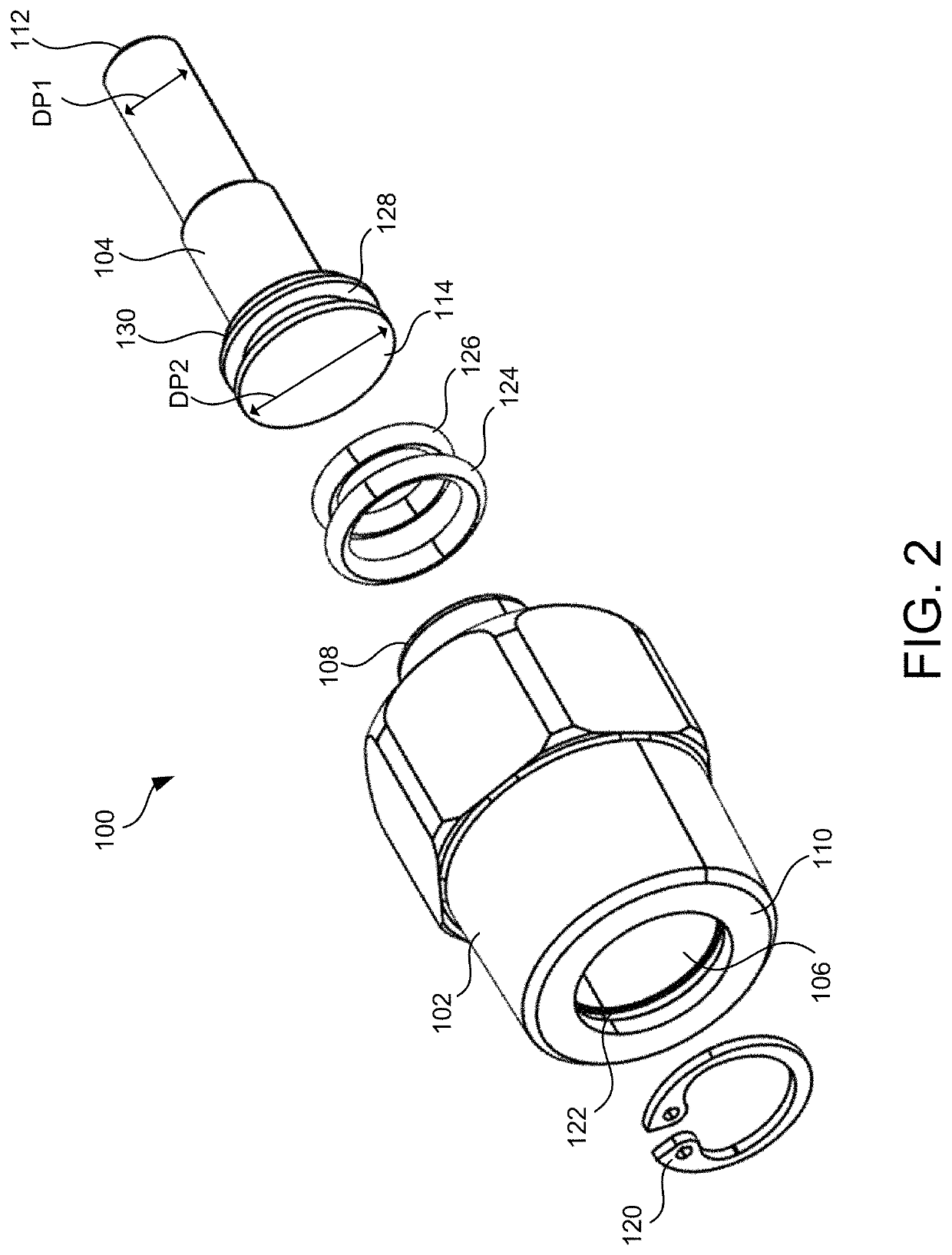
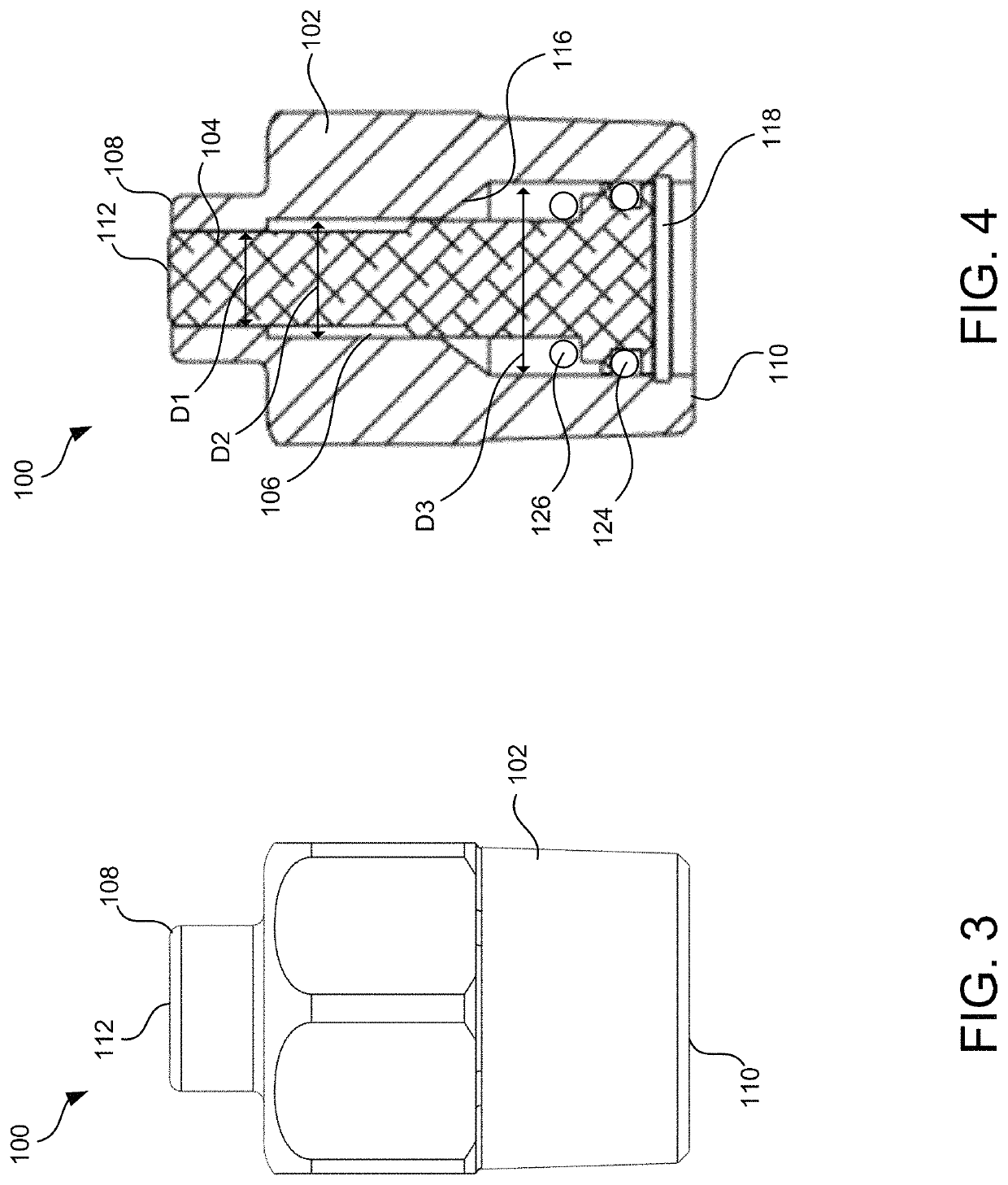
[0029]Embodiments of the present invention generally relate to indicators adapted to provide a visual indication of an over pressure situation in a system, such as a refrigeration type system. In general, the indicator (also referred to as a pop indicator), includes a main body, a piston that is disposed in the main body, and one or more O...


PUM


Abstract

An indicator adapted to provide a visual indication of an over pressure situation in a system. The indicator (also referred to as a pop indicator), includes a main body, a piston that is disposed in the main body, and one or more O-rings disposed around the piston. Initially, the piston is in a first position where the piston is retracted into the body. However, when an over pressure situation occurs, the pressure causes the piston to move in a direction out of the main body against a friction force created by the O-ring. When the piston is moved, i.e., popped, then end of the piston extending out of the body provides a visual indication.

Description

FIELD OF THE INVENTION[0001]The present invention relates generally to indicators adapted to be coupled to valves. More particularly, the present invention relates to indicators that provide a visual indication of whether a pressure relief valve has been activated.BACKGROUND[0002]Pressure relief valves are commonly used in many industries, such as the refrigeration industry. Pressure relief valves are used to control the amount of pressure within systems and containers, and flow through such systems and into and out of containers. For example, if pressure within a system or container increases too high, the pressure relief valve is activated and provides a mechanism for reducing the amount of pressure, thus protecting the system or container from pressure related failure. In general, pressure relief valves are replaced every five years, or sooner if the pressure relief valve is activated prior to the five years. However, it can be difficult and time consuming to identify whether a p...

Claims


Application Information

Patent Timeline
IPC IPC(8): F16K37/00F16K17/164F16K27/04G01L7/16F16K15/06
CPCF16K37/0058F16K15/063F16K17/164F16K27/041F16K37/005G01L7/163G01L7/166
Inventor KRUPPE, III, FRANK P.
Owner CYRUS SHANK CORP
Why Eureka
Try Eureka