Variable control orifice valve

a variable control and orifice valve technology, applied in the direction of valve housing, spindle sealing, operating means/releasing devices of valves, etc., can solve the problems of containing these substances being leakproof and much more difficult to create leak-proof systems

Active Publication Date: 2019-12-26
COMPART SYST PTE LTD
View PDF10 Cites 0 Cited by
  • Summary
  • Abstract
  • Description
  • Claims
  • Application Information

AI Technical Summary

Benefits of technology

[0006]The instant disclosure, in at least one embodiment, comprises an intake opening and an output opening in the flow body, a cavity with a first cross-sectional shape and an opening, a diaphragm or a bellows, wherein the diaphragm or the bellows seals the opening of the cavity and the diaphragm or the bellows includes a hole, a plunger with a second cross-sectional shape corresponding to the first cross-sectional shape of the cavity, wherein the plunger is longitudinally movable within the cavity and a plunger portion forms an orifice with a cavity portion, and a rod coupled with the plunger for facilitating the longitudinal movement of the plunger, wherein the rod comprises a rod cross section that corresponds to the hole in the diaphragm or the bellows.

Problems solved by technology

Additionally, the controlled flow of hazardous and toxic gases and fluids makes it imperative the system containing these substances is leakproof under any circumstances.
When the system reduces to smaller than 3 inches in diameter, especially sub 2000 micron diameters and sub 100 micron diameters, the size limitations make it much more difficult to create leak-proof systems, such as an adjustable orifice system, to control the flow of gases and liquids.

Method used


Image

  • Variable control orifice valve
  • Variable control orifice valve
  • Variable control orifice valve

Examples


Embodiment Construction

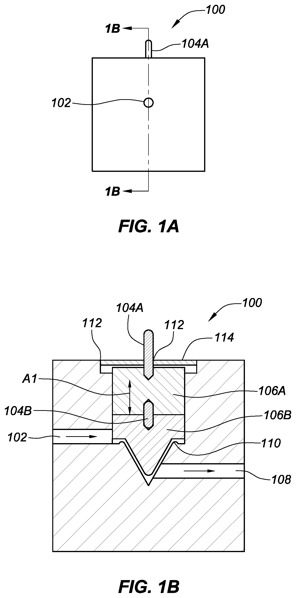
[0025]The present disclosure provides a solution to deficiencies in the design and implementation of flow control systems when size of the flow path is reduced for flow lines below 3 inches and in micron size diameter flow path. In addition, the present disclosure provides a means by which corrosive, toxic, and hazardous gases and fluids can move and be fully sealed from the outside environment. The present disclosure also implements a means of controlling the flow path of gases and fluids outside of the sealed body in which they travel.

[0026]The adjustable orifice can also be used in large scale system which allow for more elaborate drive mechanisms.

[0027]The embodiments described herein enable the user to change the orifice size without shutting the system down, opening a flow path in the flow control system, or changing the physical orifice. This can reduce the changeover time while enabling the system to accommodate adjustments to the orifice and to accommodate drops in pressure...


PUM


Abstract

An apparatus for controlling flow through a flow body comprising an intake opening and an output opening in the flow body, a cavity with a first cross-sectional shape and an opening, a diaphragm or a bellows, wherein the diaphragm or the bellows seals the opening of the cavity and the diaphragm or the bellows includes a hole, a plunger with the cross-sectional shape corresponding to the cavity, wherein the plunger is longitudinally movable within the cavity and a plunger portion forms an orifice with cavity portion, and a rod coupled with the plunger for facilitating the longitudinal movement of the plunger, wherein the rod comprises a rod cross section that corresponds to the hole in the diaphragm or the bellows.

Description

CROSS-REFERENCE TO RELATED APPLICATIONS[0001]This application claims the benefits of U.S. provisional application No. 62 / 674,689 (the '689 application), filed 22 May 2018; U.S. provisional application No. 62 / 674,695 (the '695 application), filed 22 May 2018; and U.S. provisional application No. 62 / 674,707 (the '707 application), filed 22 May 2018. The '689 application; the '695 application; and the '707 application are all hereby incorporated by reference as though fully set forth herein.FIELD OF THE DISCLOSURE[0002]The present disclosure provides a means to control and regulate the flow of gas and fluid by means of an adjustable orifice[0003]More particularly, the present disclosure addresses the shortcomings of current methods used to adjust or maintain the flow path of gas and fluid, regardless of pressure, to provide desired results.BACKGROUND[0004]In almost all markets that require precision in regard to the flow of gas and fluid, the processes demand accurate control and handl...

Claims


Application Information

Patent Timeline
Patent Type & Authority Applications(United States)
IPC IPC(8): F16K5/18F16K31/145
CPCF16K5/181F16K31/145F16K41/12F16K41/10F16K1/36F16K27/02F16K27/08
Inventor REZAEI, FREDERICK
Owner COMPART SYST PTE LTD
Why Eureka
Try Eureka