

Guidewire for a free standing intervascular device having an integral stop mechanism
- Summary
- Abstract
- Description
- Claims
- Application Information
AI Technical Summary
Benefits of technology
Problems solved by technology
Method used
Image

Examples
Embodiment Construction
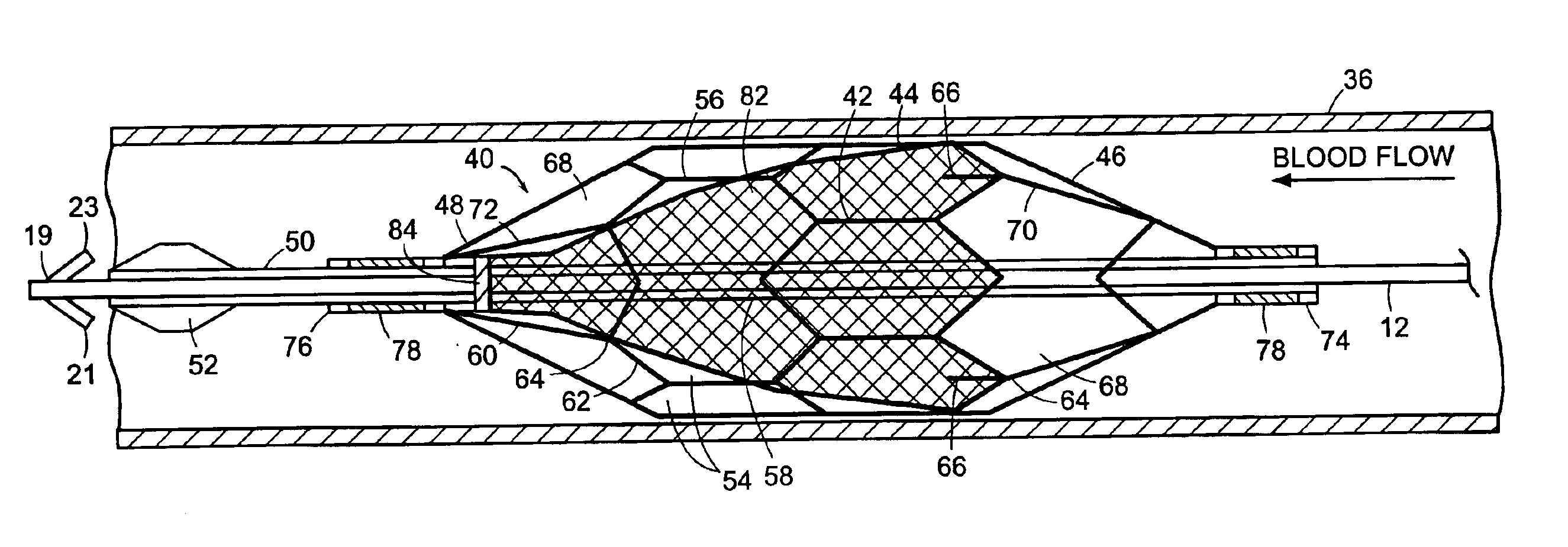
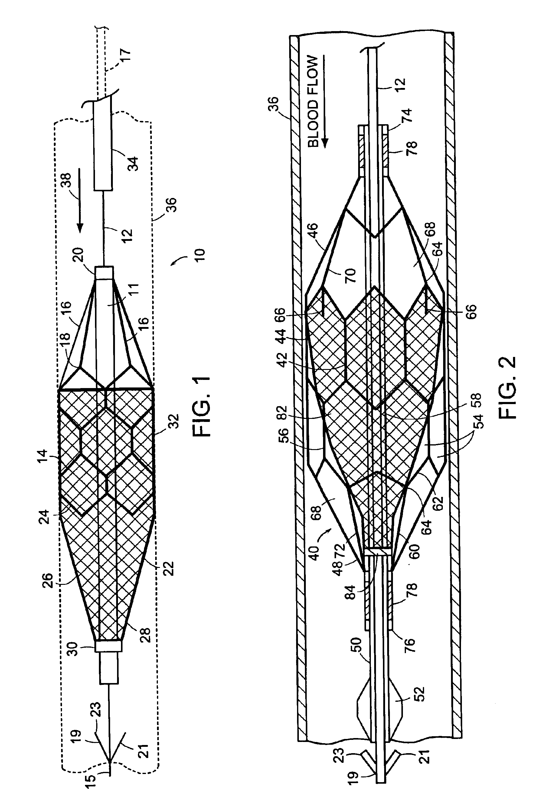
[0027]Referring to FIG. 1, a free standing filter 10 which is suitable for accommodating the guidewire 12 in accordance with the present invention is formed around a central tube 11 defining an open ended channel which forms the longitudinal axis for the filter 10 and which slidingly receives the guidewire 12. The frame of the filter is formed by a stent 14 which may be collapsed inwardly toward the tube 11 and which expands outwardly away from the tube to the substantially cylindrical open ended configuration shown in the drawings. Ideally, this stent is formed of thermal shape memory material and is of the type shown by U.S. Pat. No. 5,540,712, although other expandable stents can be used. The stent 14 is coupled at one end to the central tube 11 by elongate lead wires 16 which extend between an open proximal end 18 of the stent and a spaced coupling 20 which is secured to the central tube 11. It should be readily appreciated by those skilled in the art that the guidewire 12 in ac...
PUM
 Abstract
Description
Claims
Application Information