Ultrasound ablation catheter and method for its use

a technology of ultrasound ablation and catheter, which is applied in the field of ultrasound ablation catheter and its use, can solve the problems of ineffective epicardial ablation, shallow lesions created by rf ablation, and insufficient etc., and achieve the effect of facilitating longitudinal movement of deflection wires

Active Publication Date: 2005-01-20
BIOSENSE WEBSTER INC
View PDF45 Cites 25 Cited by
  • Summary
  • Abstract
  • Description
  • Claims
  • Application Information

AI Technical Summary

Benefits of technology

[0005] In yet another embodiment, the invention is directed to a catheter comprising an elongated catheter body having proximal and distal ends. An ultrasound transducer mounted at or near the distal end of the catheter body. The transducer has a front surface and an opposing back surface. The transducer is positioned to transmit ultrasound energy toward tissue facing the front surface but not toward tissue facing the back surface. A control handle is mounted at the proximal end of the catheter body. A deflection wire extends through the catheter body. The deflection wire has a distal end fixedly attached near the catheter body's distal end and a proximal end anchored to a mechanism in the control handle that facilitates longitudinal movement of the deflection wire relative to the catheter body. The deflection wire is anchored at a position that is about 70° to 120° relative to the direction that energy is emitted from the transducer to thereby deflect the distal end of the catheter in a direction generally transverse to the direction that energy is emitted from the transducer.

Problems solved by technology

Standard radio frequency (RF) ablation, performed using one or more electrode elements, is not very successful for epicardial ablation because it is not directional.
Further, the lesions created using RF ablation are too shallow to be effective.

Method used


Image

  • Ultrasound ablation catheter and method for its use
  • Ultrasound ablation catheter and method for its use
  • Ultrasound ablation catheter and method for its use

Examples


Embodiment Construction

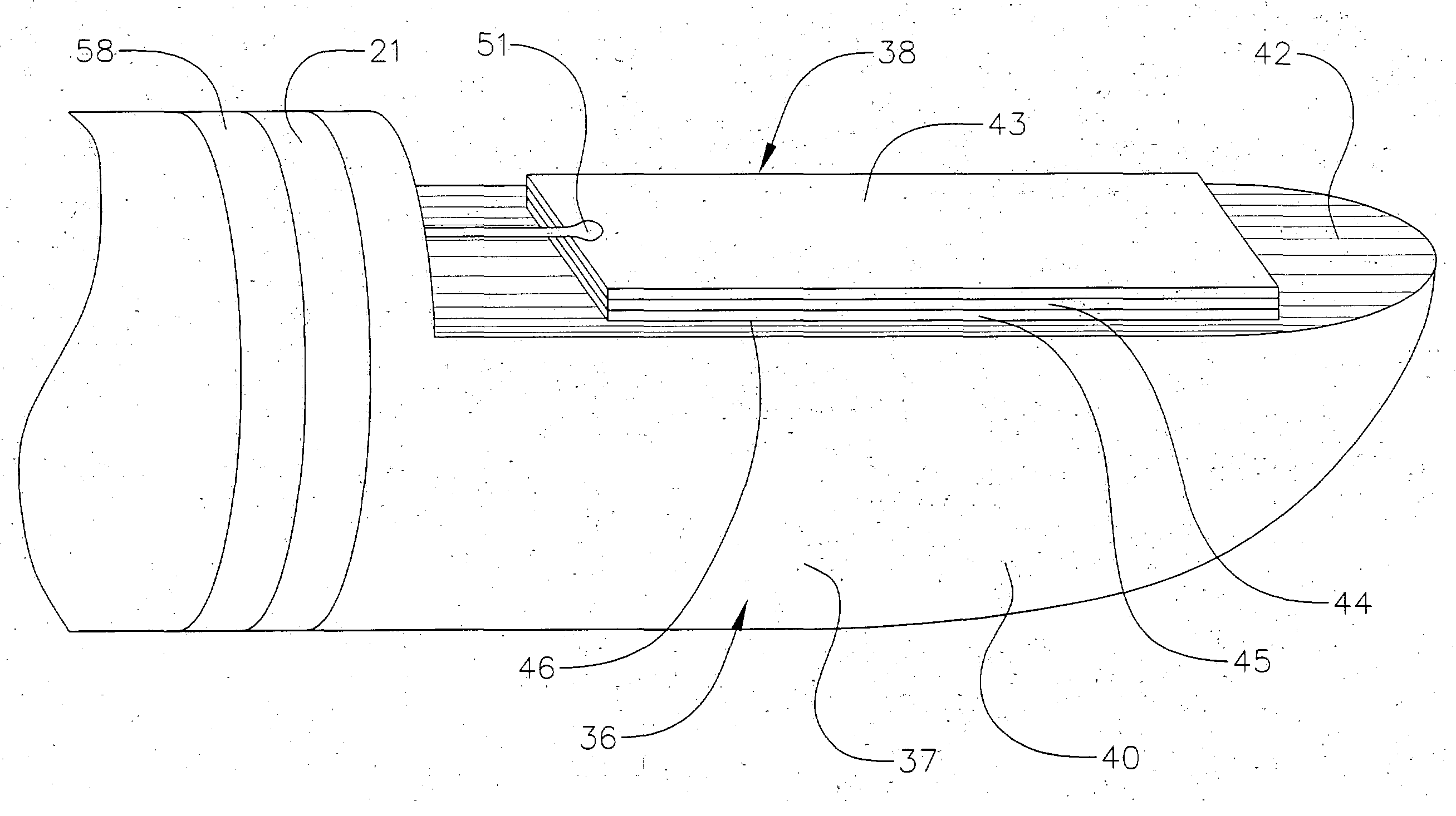
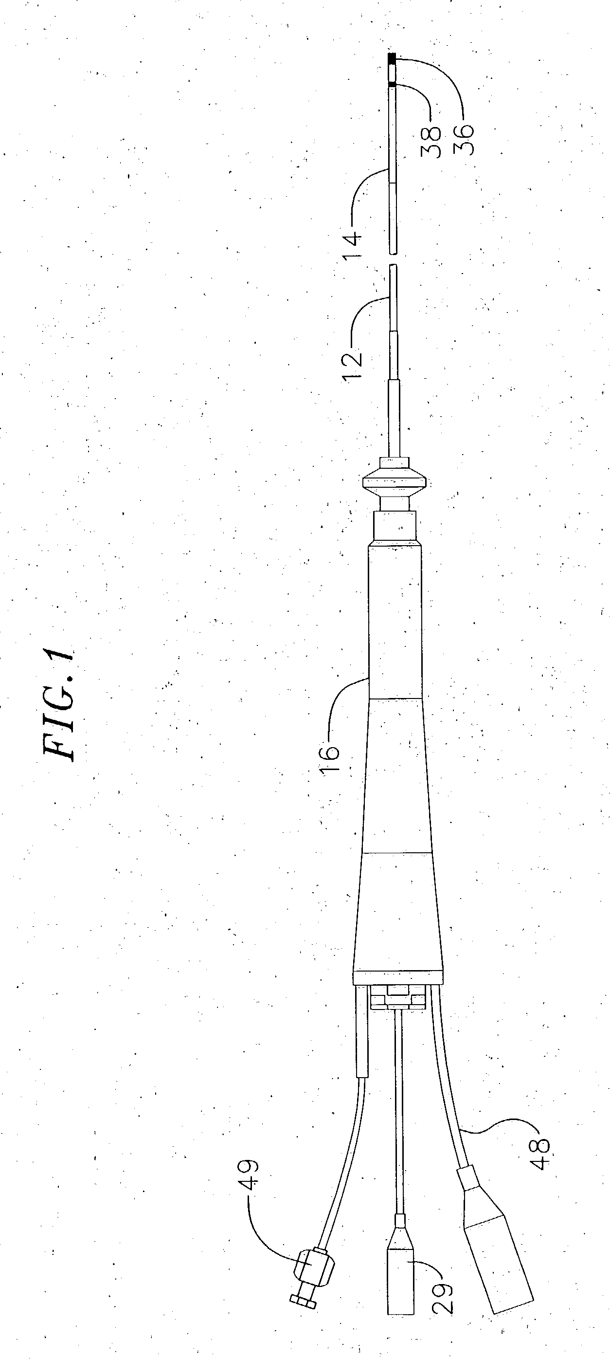
[0018] As shown in FIG. 1, the catheter comprises an elongated catheter body 10 including a proximal shaft 12 and a distal shaft 14 and a control handle 16 at the proximal end of the proximal shaft.

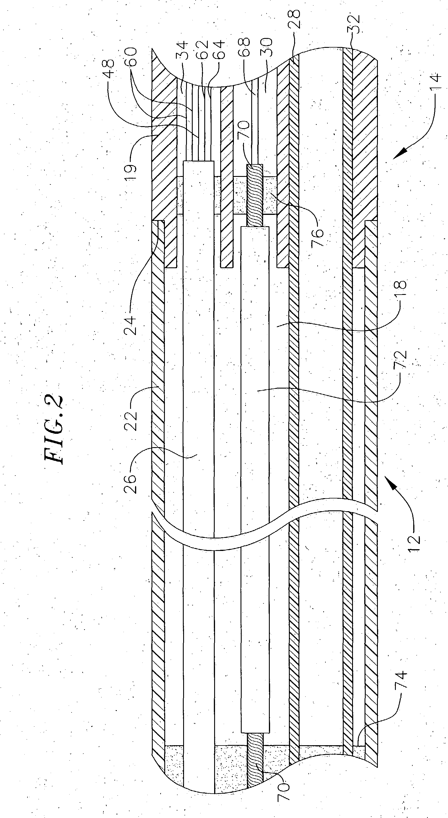
[0019] With reference to FIG. 2, the proximal shaft 12 comprises an elongated tubular construction having a single, axial or central lumen 18. The proximal shaft 12 is flexible, i.e., bendable, but substantially non-compressible along its length. The proximal shaft 12 can be of any suitable construction and made of any suitable material. A presently preferred construction comprises an outer wall 22 made of a polyurethane or nylon. The outer wall 22 comprises an imbedded braided mesh of stainless steel or the like to increase torsional stiffness of the catheter body 10 so that, when the control handle 16 is rotated, the distal shaft 14 will rotate in a corresponding manner.

[0020] The outer diameter of the proximal shaft 12 is not critical, but is preferably no more than about 8 french, m...


PUM


Abstract

Catheters and methods for epicardial ablation are provided. A suitable catheter comprises an elongated catheter body and an ultrasound transducer mounted at or near the distal end of the catheter body. The transducer has a front surface and an opposing back surface, wherein the transducer is positioned to transmit ultrasound energy toward tissue facing the front surface but not toward tissue facing the back surface. A sensor is mounted within the catheter near the ultrasound transducer for sensing a location and an orientation of the ultrasound transducer within a patient. A suitable method involves introducing the distal end of the catheter introducing into the pericardium of a patient. The transducer's front surface is positioned so that it generally faces tissue to be ablated, and the tissue is ablated with ultrasound energy generated by the transducer.

Description

BACKGROUND [0001] Standard radio frequency (RF) ablation, performed using one or more electrode elements, is not very successful for epicardial ablation because it is not directional. RF ablation creates a lesion that burns the tissue in all directions, thereby burning the pericardium. As the burned pericardium heals, it tends to adhere to the epicardial tissue. Further, the lesions created using RF ablation are too shallow to be effective. Thus, a need exists for a catheter that is particularly effective for epicardial ablation. SUMMARY OF THE INVENTION [0002] The invention is directed to catheters and methods for epicardial ablation using ultrasound energy. In one embodiment, the invention is directed to a catheter that is particularly useful for epicardial ablation. The catheter comprises an elongated catheter body having proximal and distal ends. An ultrasound transducer is mounted at or near the distal end of the catheter body. The transducer has a front surface and an opposing...

Claims


Application Information

Patent Timeline
Patent Type & Authority Applications(United States)
IPC IPC(8): A61B8/12A61B17/00A61B17/22A61B19/00
CPCA61B8/12A61B17/2202A61B2017/00084A61B8/445A61B2018/00392A61B2019/5278A61B2017/00247A61B2090/3782
Inventor KEIDER, YARON
Owner BIOSENSE WEBSTER INC
Why Eureka
Try Eureka