Air lock system

a technology of air lock and self-cleaning, which is applied in the direction of engine seals, flanged joints, pipe joints, etc., can solve the problems of ineffective system, difficult to maintain tightness and connect pipes, and even worse, so as to preserve tightness and clean the connection point

Pending Publication Date: 2019-12-26
BIOFORCETECH
View PDF0 Cites 1 Cited by
  • Summary
  • Abstract
  • Description
  • Claims
  • Application Information

AI Technical Summary

Benefits of technology

[0007]Embodiments of the present disclosure include a system to connect two or more pipes which have to be frequently connected and disconnected in a way in which not only preserves tightness

Problems solved by technology

In that case, it is often very hard to maintain the tightness and to connect the pipes with precision one time after the other.
The problem, as recalled above, is even worse if an industrial process requires the pipe to connect and disconnect continuously.
In the past, the problem of creating a tight connection between two often disconnecting pipes has been solved by a syst

Method used


Image

  • Air lock system
  • Air lock system
  • Air lock system

Examples


Embodiment Construction

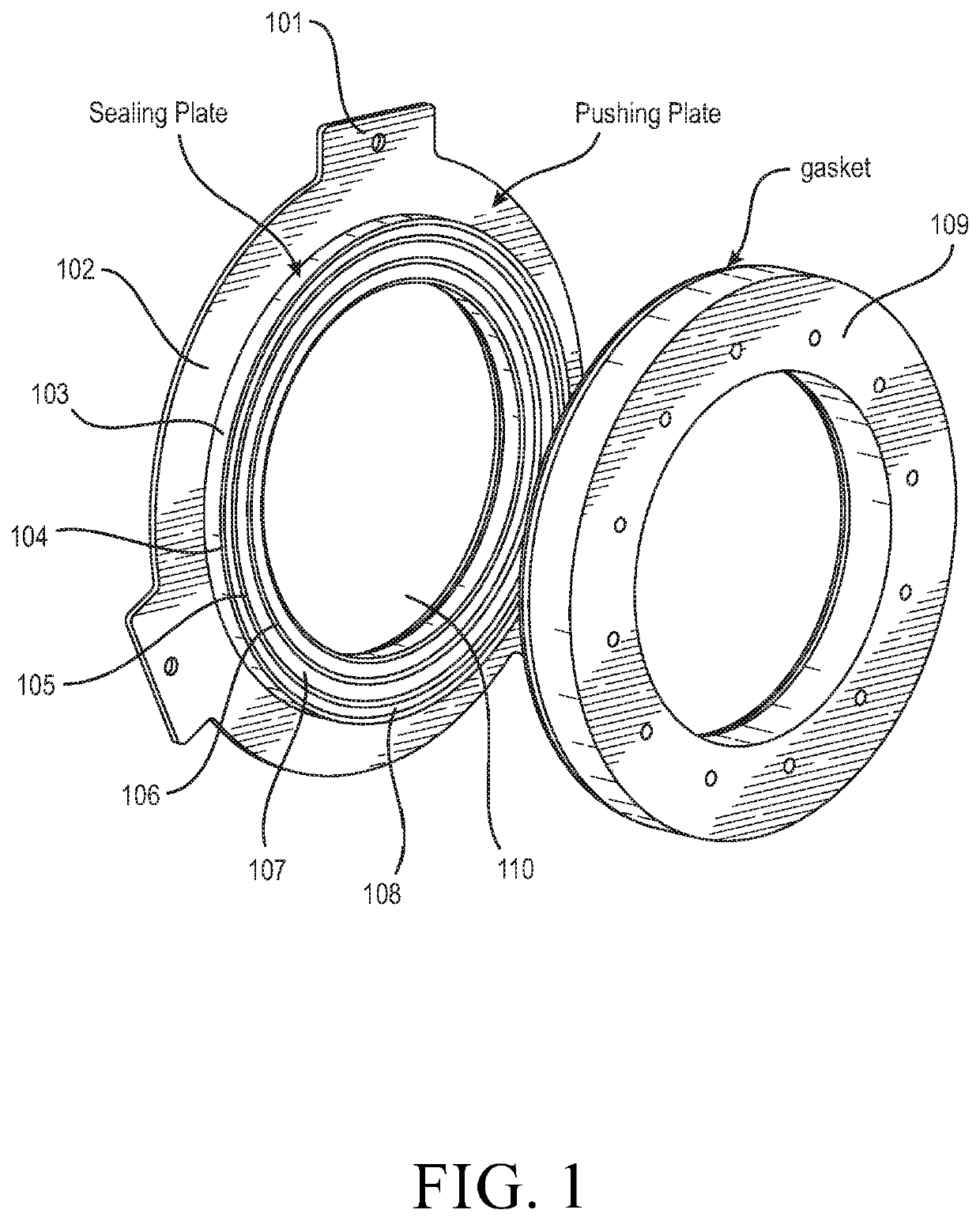
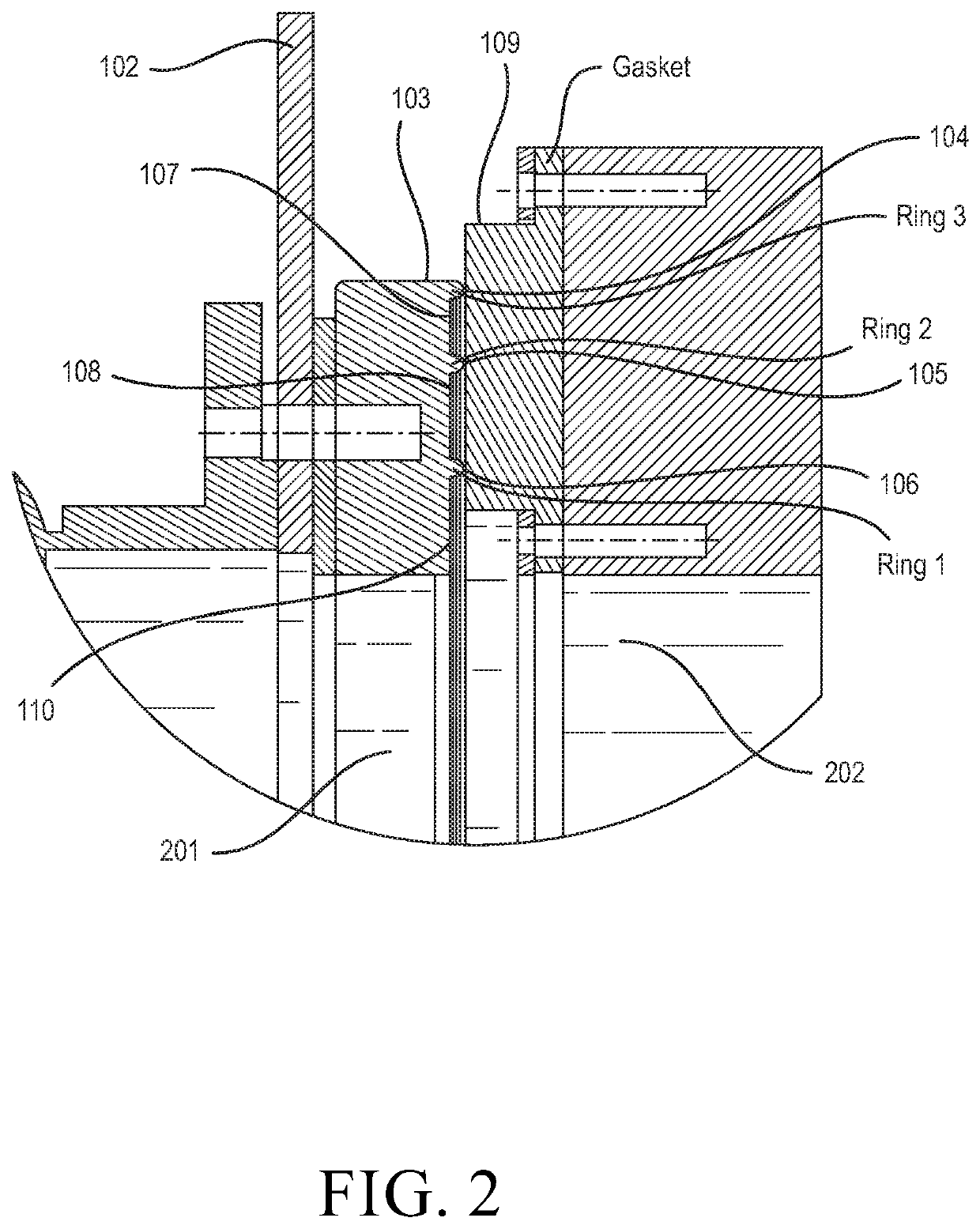
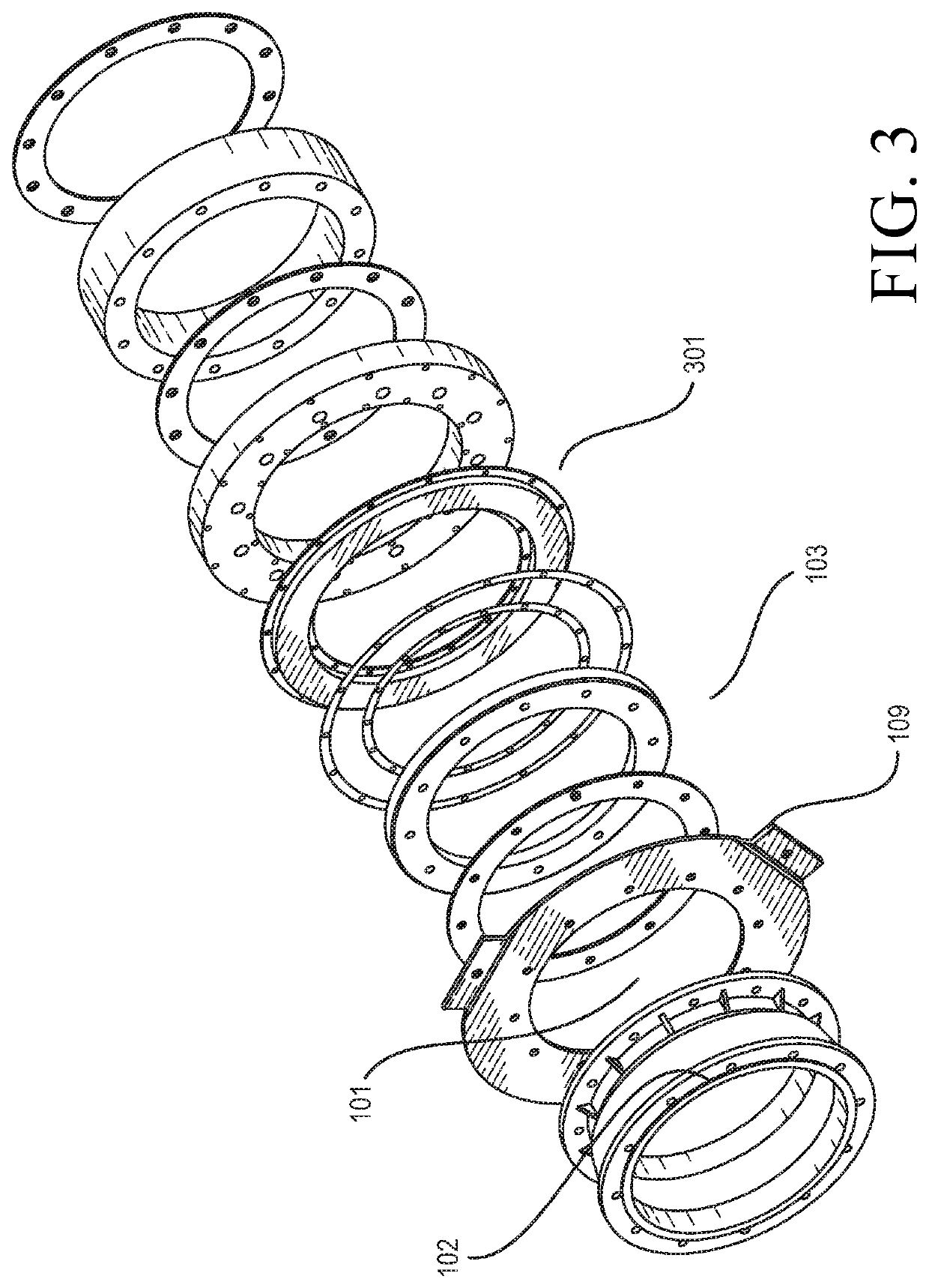
[0017]Embodiments of the present disclosure comprise a method and a system to efficiently connect two 201, 202 or more pipes together, even when the pipes 201, 202 rotate, translate or both. The efficiency of the connection is guaranteed by the combined use of pushing plates 102, sealing plates 103 and gaskets 109. In particular, in one of the embodiments of the invention the sealing plate contains multiple, concentric, protuberances 104, 105, 106. The protuberances 104, 105, 106 can also referred to as “rings”. Such rings are located at a certain distance 107,108 one from the other so as to allow the pipe connection to be flexible: If the pipes 201, 202 are perfectly or almost perfectly aligned, the first ring 106 is used and the pipe 202 goes directly into that ring 106. If for some reason the pipes 201, 202 are not perfectly aligned, then the next concentric ring 105 is involved and it is used to connect the pipes 201,202 while preserving the tightness. And this system can be rep...


PUM


Abstract

The techniques introduced here include a system and method for efficiently connecting two or more pipes through the combination of a pushing plate, a gasket and a sealing plate. Such techniques exploit the presence of concentric protuberances, or rings, on the sealing plate that help, also thanks to the space between them, in keeping the cleanness, tightness and flexibility of the conjunction, especially when sticky substances, like a sludge, are dealt with.

Description

FIELD OF THE INVENTION[0001]The invention generally relates to a self-cleaning, flexible and tight system for connecting two or more pipes.BACKGROUND OF THE INVENTION[0002]Valves and pipe connectors in general are commonly used when two or more pipes have to be connected or reconnected together. Their function is not merely to make air, a fluid or other substances to go from one pipe to another pipe but they also need to have other characteristics.[0003]In particular, in peculiar contexts, pipe connectors have to ensure the tightness of the connection, so that no air, liquid or other material (at least to a certain extent) drops out from the connection between the two pipes, including in the moment they are connected and / or disconnected.[0004]The above-referenced need is exacerbated when the pipes to be connected do not remain in a fixed position for a long time, but they have to be detached and reconnected very often as part of an industrial process. In that case, it is often very ...

Claims


Application Information

Patent Timeline
IPC IPC(8): F16L23/24F16L23/16F16J15/02
CPCF16L23/24F16L23/162F16J15/028F16J15/106
Inventor PRESEZZI, DARIOVILLA, VALENTINOMOSCIARELLO, MARCOPESSINA, STEFANOBONFANTI, MATTIA
Owner BIOFORCETECH
Why Eureka
Try Eureka