Pressure-type flow rate control device

a flow rate control and flow rate technology, applied in the direction of diaphragm valves, valve housings, instruments, etc., can solve the problem of extremely poor fall response of gas, and achieve the effect of improving fall characteristics, efficient utilization, and pressure control

Active Publication Date: 2016-12-01
FUJIKIN INC
View PDF17 Cites 13 Cited by
  • Summary
  • Abstract
  • Description
  • Claims
  • Application Information

AI Technical Summary

Benefits of technology

[0029]According to the invention of the present application, by providing the configuration where the fluid passage goes through the pressure detection chamber, the inner capacity of the fluid passage between the control valve for pressure control and the orifice can be reduced than in a conventional example, and as a result the fall characteristics can be improved.
[0030]Moreover, by arranging the pressure sensor below the control valve for pressure control and vertically extending the fluid passage (first passage portion) connecting the two components from the control valve for pressure control into the pressure detection chamber, the two components can be connected in the shortest distance, and the inner capacity of the fluid passage between the control valve for pressure control and the orifice can be reduced.
[0031]Moreover, a first passage portion and a second passage portion are provided on end portions of the pressure detection chamber, whereby the pressure detection chamber used as the fluid passage can be efficiently utilized, which can contribute to the reduction in the inner capacity of the fluid passage between the control valve for pressure control and the orifice.
[0032]Moreover, by giving the ring gasket which defines the height of the pressure detection chamber a cross-sectional shape whose sealing face is caused to lean to the inner circumferential surface side, the area of the sealing face necessary for ensuring the sealing performance can be maintained, and at the same time the inner circumferential surface can be approached to the flat surface to reduce the capacity of the space surrounded by the inner circumferential surface. This can contribute to the reduction in the inner capacity of the fluid passage between the control valve for pressure control and the orifice.

Problems solved by technology

However, the pressure-type flow rate control device FCS of this type has poor replaceability of the gas since the orifice OL with a minute diameter is used, and has the problem that the so-called fall response for the gas is extremely poor when the control valve for pressure control CV of the pressure-type flow rate control device FCS is closed and the output side is released as it takes long time to discharge the gas in a space portion between the control valve CV and the orifice OL.

Method used


Image

  • Pressure-type flow rate control device
  • Pressure-type flow rate control device
  • Pressure-type flow rate control device

Examples


first embodiment

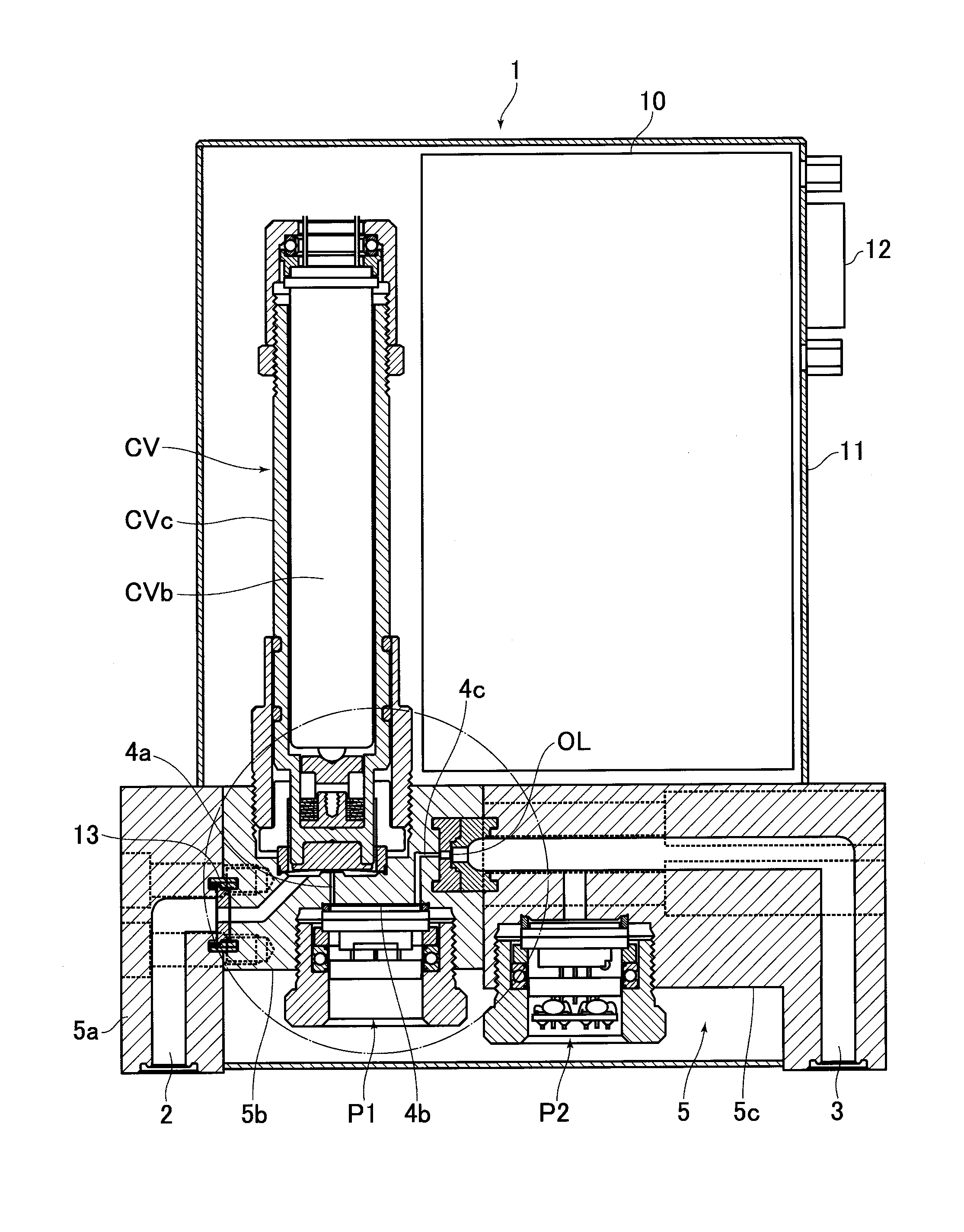
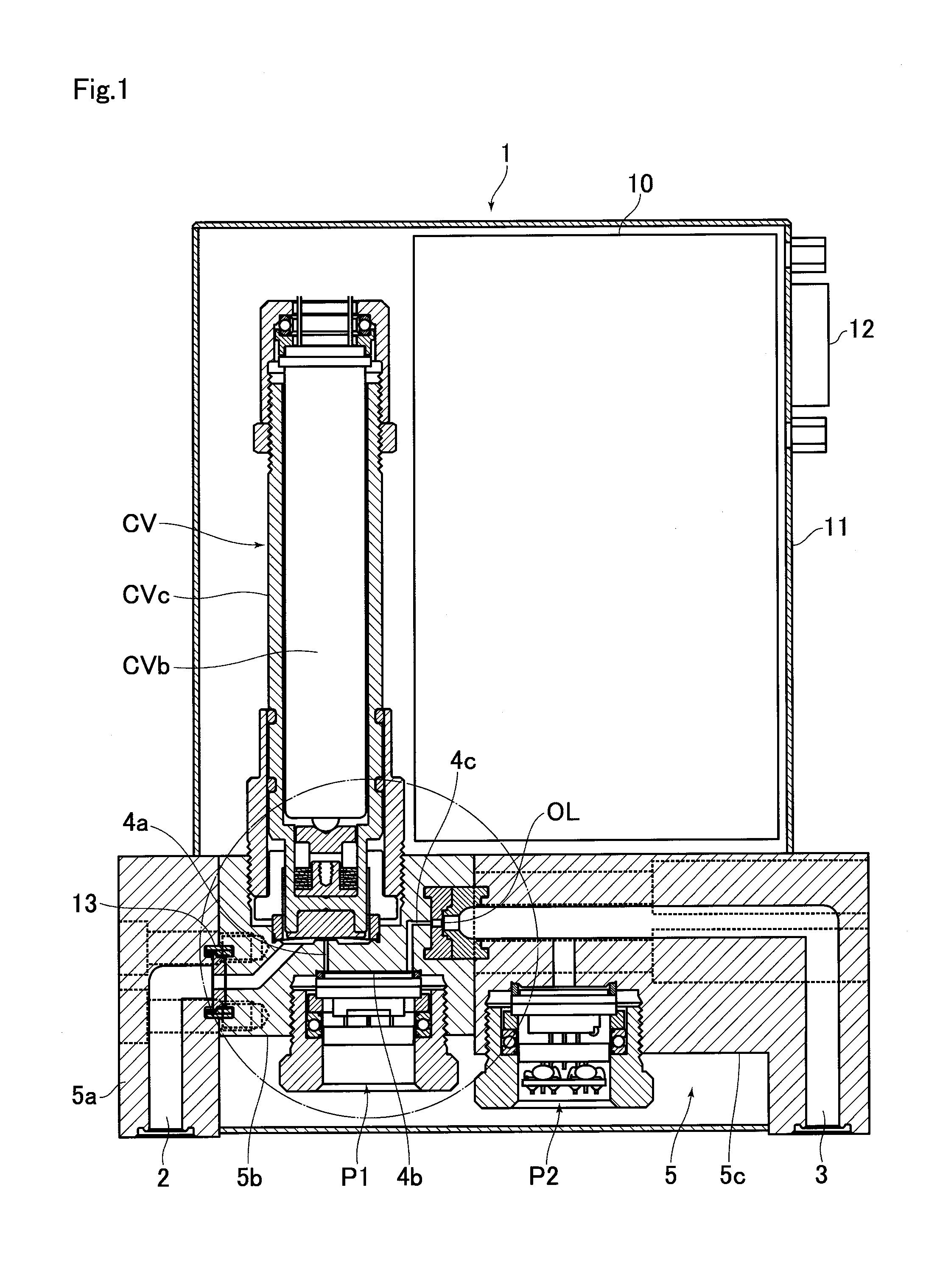
[0044]FIG. 1 shows a cross-sectional view of the pressure-type flow rate control device according to the present invention, and FIG. 2 shows an enlarged diagram of a portion surrounded by the chain-line circle in FIG. 1. A pressure-type flow rate control device 1 includes a body 5 provided with a fluid passage 4 which communicates a fluid inlet 2 and a fluid outlet 3, a control valve for pressure control CV which is fixed to the body 5 to open and close the fluid passage 4, an orifice OL arranged in the course of the fluid passage 4 on the downstream side of the control valve for pressure control CV, and a pressure sensor P1 which is fixed to the body 5 to detect the internal pressure of the fluid passage 4 between the control valve for pressure control CV and the orifice OL, the fluid passage 4 including a first passage portion 4a which connects the control valve for pressure control CV and a pressure detection chamber 4b on a pressure detection surface P1a (FIG. 2) of the pressure...

second embodiment

[0059]FIG. 5 is a cross-sectional view which shows the pressure-type flow rate control device according to the present invention. The components similar to those in the embodiment in FIG. 1 will be referred to by the same numerals and their repeated explanation will be omitted.

[0060]The pressure-type flow rate control device 1 of the second embodiment is different from the above first embodiment in that it has a third passage portion 4f connected to the first passage portion 4a in place of the second passage portion 4c of the above first embodiment, and the other configurations similar to that in the above first embodiment. Also in the second embodiment, the arrangement of the control valve for pressure control CV and the pressure sensor P1 and the arrangement structure of the first passage portion 4a are the same in the first embodiment, whereby the inner capacity of the fluid passage 4 which is related to the fall time can be reduced.

[0061]The present invention is not limitedly in...


PUM


Abstract

A pressure-type flow rate controller includes a body provided with a fluid passage which communicates a fluid inlet and a fluid outlet, a control valve for pressure control fixed to the body to open and close the fluid passage, an orifice arranged in the course of the fluid passage on the downstream side of the control valve, and a pressure sensor fixed to the body to detect the internal pressure of the fluid passage between the control valve and the orifice, wherein the fluid passage comprises a first passage portion communicating the control valve and a pressure detection chamber provided on a pressure detection surface of the pressure sensor, and a second passage portion spaced away from the first passage portion and communicating the pressure detection chamber and the orifice.

Description

TECHNICAL FIELD[0001]The present invention relates to an improvement of a pressure-type flow rate control device, and especially to a pressure-type flow rate control device with greatly increased operation performance of a material gas supply apparatus for semiconductor manufacturing devices and the like by enhancing fall response.BACKGROUND ART[0002]Heretofore, in a material gas supply apparatus for semiconductor manufacturing devices and the like, thermal flow rate control devices and pressure-type flow rate control devices are widely used for controlling the flow rates of supplied gases. Especially, as shown in FIG. 6, a pressure-type flow rate control device FCS is constituted by a control valve for pressure control CV, a temperature detector T, a pressure sensor P, an orifice OL, a calculation control unit CD consisting of a temperature correction / flow rate calculation circuit CDa, a comparator circuit CDb, input output circuit CDc, output circuit CDd and other components, and ...

Claims


Application Information

Patent Timeline
Patent Type & Authority Applications(United States)
IPC IPC(8): G05D7/06H01L21/67F16K7/14
CPCG05D7/0635H01L21/67069F16K7/14F16K31/007H01L21/67253F16K27/00
Inventor HIROSE, TAKASHIYOSHIDA, TOSHIHIDEMATSUMOTO, ATSUSHIHIRATA, KAORUIKEDA, NOBUKAZUNISHINO, KOUJIDOHI, RYOUSUKESUGITA, KATSUYUKI
Owner FUJIKIN INC
Why Eureka
Try Eureka