Cover for cable connectors

a technology for cable connectors and covers, which is applied in the direction of couplings/cases, coupling device connections, and securing/insulating coupling contact members. it can solve the problems of connectors, signal quality degradation, and transmission line components such as connectors

Active Publication Date: 2013-04-16
JOHN MEZZALINGUA ASSOC INC
View PDF105 Cites 14 Cited by
  • Summary
  • Abstract
  • Description
  • Claims
  • Application Information

AI Technical Summary

Benefits of technology

[0010]It is therefore a principal object and advantage of the present invention to provide a cover for cable connectors or other components that may be quickly installed and / or removed.
[0011]It is another object and advantage of the present invention to provide a cable component cover that protects the cable connectors or other components from the environment.
[0012]It is yet another object and advantage of the present invention to provide a cable component cover that maintains its sealing properties regardless of temperature fluctuations.
[0013]It is a further object and advantage of the present invention to provide a cable connector cover that may be used in conjunction with other cable connector covers of various sizes and / or shapes.
[0014]Other objects and advantages of the present invention will in part be obvious, and in part appear hereinafter.
[0015]In accordance with the foregoing objects and advantages, a first aspect of the present invention provides a cover for a connector adapted to terminate a cable, wherein the connector includes a body portion and is adapted to terminate in a bulkhead. The cover comprises an elongated body comprising cable and bulkhead ends, interior and exterior surfaces, and the elongated body extends along a longitudinal axis. The interior surface includes a first region adapted to cover at least a portion of the cable and extends from the cable end to a first shoulder, wherein the first region is of a minimum, first cross-sectional diameter. The interior surface further includes a second region which is adapted to cover at least the connector body portion and which extends from the first shoulder to a second shoulder. The second region has a minimum, second cross-sectional diameter that is greater than the minimum, first cross-sectional diameter. The interior surface further includes a third region which is adapted to cover at least a portion of the connector and which extends from the second shoulder to the bulkhead end. The third region has a minimum, third cross-sectional diameter that is greater than the minimum, second cross-sectional diameter.

Problems solved by technology

Transmission line components such as connectors are often exposed to the open environment and are thus susceptible to degradation from weather related corrosive effects (e.g., moisture infiltration), pollution, debris and other elements.
Degradation of the components potentially leads to degradation of the signal quality being transmitted through the cables.
First, the taping requires significant time in its initial installation, and needs to be removed in order to gain access to the component when servicing the components (and then reapplied after servicing is complete). The time associated with the taping and removal thereof when servicing the components is costly. In addition, the quality of the seal is dependant on the skill of the worker that is applying the tape. As such, inconsistent application of the tape may lead to instances of ineffective sealing of components.
Second, the properties inherent in the material composition of the tape subjects the tape to size fluctuation and inconsistent adherence. If the tape contracts in colder temperatures and loses adherence strength in warmer temperatures, for example, the quality of the seal created through the tape becomes compromised in regions that experience wide temperature fluctuation. In addition, the same pollutants and other environmental factors that affect the components when unsealed may also affect the sealing quality of the tape.
While the opening and closing of the clamshell style cover facilitates quicker installation and removal in repair situations, it too is not without its drawbacks.
For instance, the plastic material becomes brittle in colder temperatures, and this reduction in ductility increases over time.
As the material becomes more brittle, the closure mechanisms lose their effectiveness often breaking or otherwise not reliably performing the closure function for which they were designed.
Furthermore, the clamshell style closures include seams that extend essentially the entire periphery of the cover, making the sealing function much more difficult when compared to covers that do not include such long seams between parts.
As such, the clamshell style covers lose their sealing effectiveness over time and in climates that routinely experience cold temperatures.

Method used


Image

  • Cover for cable connectors
  • Cover for cable connectors
  • Cover for cable connectors

Examples


Embodiment Construction

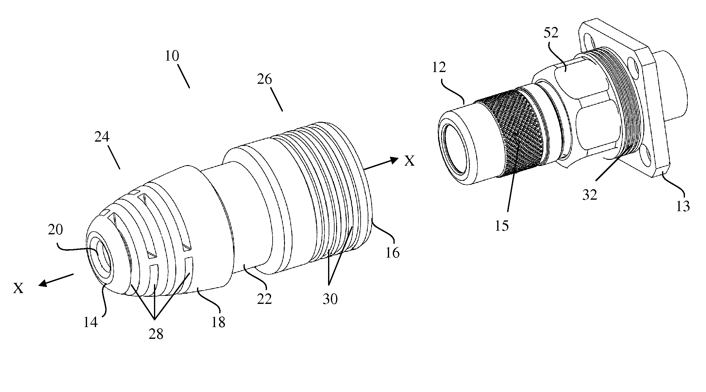
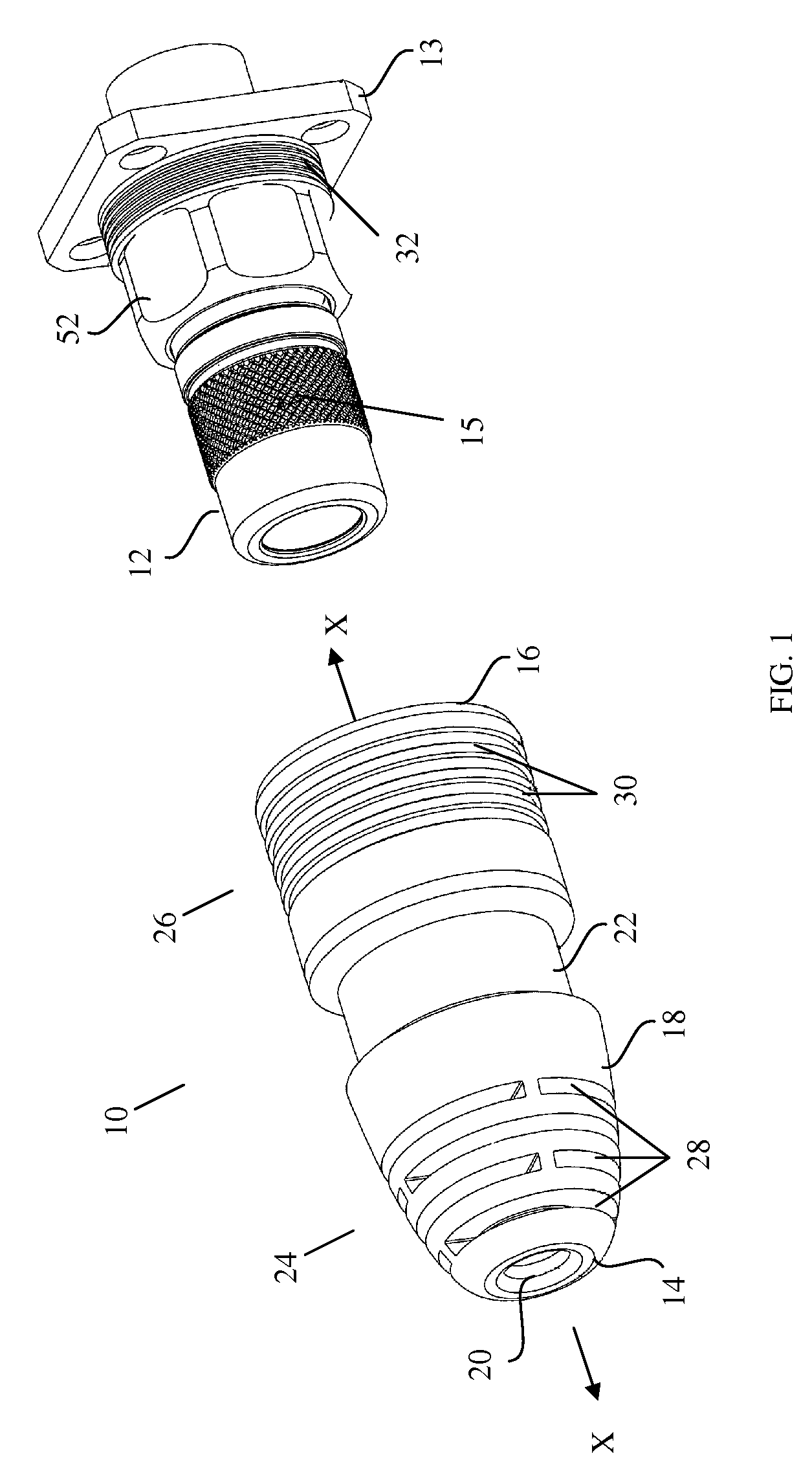
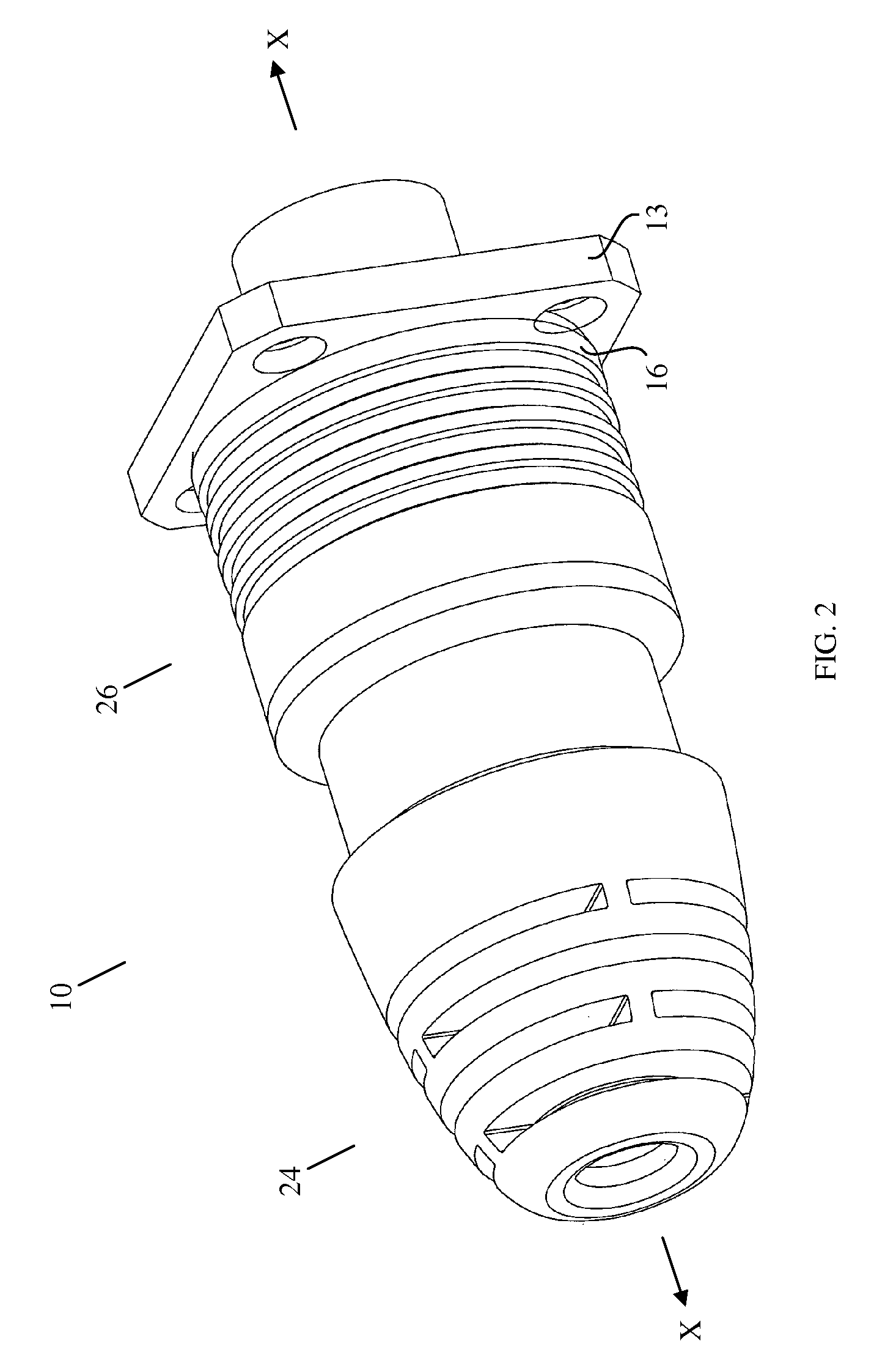
[0030]Referring now to the drawings, wherein like reference numerals refer to like parts throughout, there is seen in FIG. 1 a cover, designated generally by reference numeral 10, adapted to be placed in secure and sealing relation over a connector 12 (such as a 5-series connector manufactured by John Mezzalingua Associates, Inc. of East Syracuse, N.Y. that is adapted to terminate a ⅞″ cable). Connector 12 terminates on a bulkhead 13. In the embodiment of FIG. 1, cover 10 comprises: an elongated body composed of a rubber material that exhibits a low modulus of elasticity over an extended temperature range, preferably a silicone rubber, that extends along a longitudinal axis X-X; a cable end 14; bulkhead end 16; exterior surface 18; interior surface 20; and an annular groove 22 of reduced diameter (when compared to the other sections of cover 10 as defined below) formed at a medial position in exterior surface 18. The rubber composition of the cover 10 permits it to elastically defor...


PUM


Abstract

A cover and a system of covers for placement in sealed relation over a connector or a pair of connectors that is or are adapted to terminate a cable or splice together a pair of cables. The covers include a cable end that sealingly receives a cable therein, an elongated body that provides secure cover to a cable connector, and an end that abuts a bulkhead or sealingly engages with a second cover when used in a splicing application. For spliced cables, an adapter may be fitted into a gap between surfaces of the first and second covers to provide sealing.

Description

CROSS-REFERENCE TO RELATED APPLICATIONS[0001]The present application relates to the subject matter of applicant's U.S. patent application Ser. No. 12 / 398,857, now U.S. Pat. No. 7,731,512, the entirety of which is hereby incorporated by reference.BACKGROUND OF THE INVENTION[0002]1. Field of the Invention[0003]The present invention relates to covers for cable connectors, and, more specifically, to covers that protect cable connectors from environmental degradation.[0004]2. Description of the Related Art[0005]Transmission line components such as connectors are often exposed to the open environment and are thus susceptible to degradation from weather related corrosive effects (e.g., moisture infiltration), pollution, debris and other elements. Degradation of the components potentially leads to degradation of the signal quality being transmitted through the cables.[0006]To protect the components from environmental effects, layers of tape have been used to cover and seal the components, c...

Claims


Application Information

Patent Timeline
Patent Type & Authority Patents(United States)
IPC IPC(8): H01R13/52
CPCH01R13/5213H01R13/639
Inventor MONTENA, NOAH
Owner JOHN MEZZALINGUA ASSOC INC
Why Eureka
Try Eureka