Ball screw with sectional circulating assemblies

Active Publication Date: 2013-03-07
HIWIN TECH
View PDF7 Cites 13 Cited by
  • Summary
  • Abstract
  • Description
  • Claims
  • Application Information

AI Technical Summary

Benefits of technology

[0018]The primary object of the present invention is to provide a ball screw with sectional circulating assemblies, wherein the helical groove doesn't nee

Problems solved by technology

First, although this circulating element 13 has the advantages of smooth rolling path and high rotation speed, since the nail portion 14 is engaged in the helical groove 101 of the screw shaft 11, any end of the helical groove 101 must be open so as to facilitate the installation of the nail portion 14 of the circulating element 13. In other words, the helical groove must extends to the shoulder portion of the screw shaft 11, and the helical groove leaves a notch in the in the abutting surface of the shoulder portion, as a result, the integrality of the diameter of the abutting surface is damaged (the outer periphery of the abutting surface is not round). When both ends of the screw shaft 11 are mounted on bearing seats of a machine (not shown), and the motor of the machine starts to rotate the screw shaft 11, the rotation inertia will effect an axial load on both ends of the screw shaft 11. And due to the integrality of the diameter of the abutting surface is damaged, the axial load cannot be evenly distributed on the both ends of the screw shaft 11. This will generate great pressure against the end surface (not shown) of the bearing seats, causing damage to the bearing seats, as a result of that, the screw shaft 11 will be deformed during rotation, adversely affecting the circulation of the rolling balls, but will

Method used


Image

  • Ball screw with sectional circulating assemblies
  • Ball screw with sectional circulating assemblies
  • Ball screw with sectional circulating assemblies

Examples


Embodiment Construction

[0052]The present invention will be clearer from the following description when viewed together with the accompanying drawings, which show, for purpose of illustrations only, the preferred embodiment in accordance with the present invention.

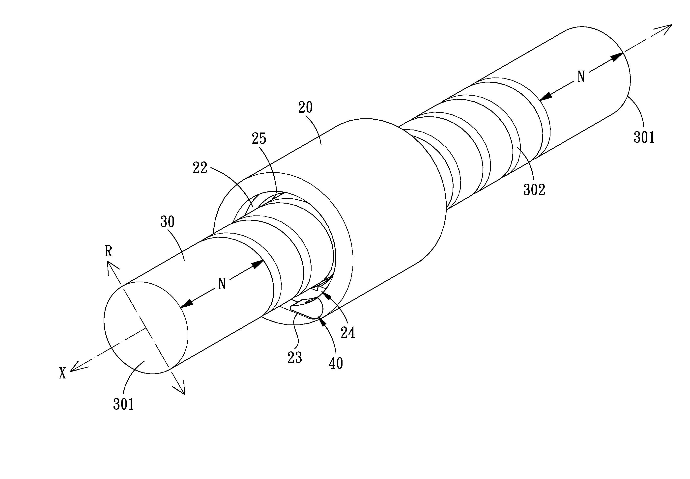
[0053]Referring to FIGS. 4-13, a ball screw with sectional circulating assemblies in accordance with a first embodiment of the present invention is illustrated and comprises: a nut 20, a screw shaft 30, two circulating assemblies 40 and a plurality of rolling balls 60.

[0054]The screw shaft 30 is an elongated structure extending in a direction, the direction in which the screw shaft 30 extends is defined as an axial direction X, and a direction normal to the axial direction X is defined as a radial direction R. The screw shaft 30 is provided with two axial end surfaces 301 and an outer peripheral surface between the two axial end surfaces 301. The outer peripheral surface of the screw shaft 30 is formed with a helical groove 302, and both ends of ...


PUM


Abstract

A ball screw with sectional circulating assemblies comprises an inner circulating block and an outer circulating block. In assembly, the inner circulating block is initially placed between the screw shaft and the nut before the rolling balls and the screw shaft are positioned, thus preventing the rolling balls from dropping out and the interference with the threads of the screw shaft. After the rolling balls and the screw shaft are positioned, the outer circulating block is placed into the nut and engaged with the inner circulating block, and the outer circulating block is fixed to the nut. This method can maintain the tightness of the nut, thus preventing the leakage of noise.

Description

[0001]This application is a continuation in part of U.S. patent application Ser. No. 13 / 225,397, which claims the benefit of the earlier filing date of Sep. 2, 2011. Claim 1 of this application is revised from claim 1 of the U.S. patent application Ser. No. 13 / 225,397, and claim 2 of this application is new.BACKGROUND OF THE INVENTION[0002]1. Field of the Invention[0003]The present invention relates to a ball screw, and more particularly to a ball screw with sectional circulating assemblies, which can be easily assembled and produces less noise.[0004]2. Description of the Prior Art[0005]Nowadays, ball screw is used more and more widely in modern industries. As a linear transmission means, the ball screw not only has high precision but also has the advantages of low frictional loss, high energy conversion ratio, low noise and high rigidity. Hence, it is self-evident that the ball screw is very important to various industrial mechanisms. In order for the rolling balls between the scre...

Claims


Application Information

Patent Timeline
IPC IPC(8): F16H25/22B23P11/00
CPCF16H25/2219Y10T74/19772Y10T29/49826
Inventor PAN, HUNG-SUNGWU, WEN-CHIA
Owner HIWIN TECH
Why Eureka
Try Eureka