Energy storage device and method of manufacturing the same

a technology of energy storage and manufacturing method, which is applied in the direction of sustainable manufacturing/processing, coupling device connection, electrical apparatus casing/cabinet/drawer, etc., can solve the problems of shortening the positive and negative electrodes, affecting the ability and affecting the stability of the sealing structure of the energy storage device. , to achieve the effect of enhancing the capability of the whole energy storage device and keeping the sealing structure stabl

Inactive Publication Date: 2012-10-18
CYNTEC
View PDF5 Cites 13 Cited by
  • Summary
  • Abstract
  • Description
  • Claims
  • Application Information

AI Technical Summary

Benefits of technology

[0009]An objective of the invention is to provide an energy storage device, which has a metal coating layer capable of keeping a sealing structure of the energy

Problems solved by technology

Some electrolyte may leak due to compression induced in a press fitting process.
Besides, if the force of the press fitting is unstable or the disposition of the gasket is incorrect, the gasket tends to be cracked during the press fitting process, leading to a short of the positive and negative electrodes.
Furthermore, the energy storage device of the coin type is easily deformed by a heat impact during product assembly, so that a crack occurs between the upper cover and the bottom cover leading to leakage of the electrolyte along the crack.
In addition, because the energy storage devices of the coin type are sealed by press fitting, the layout area therefor is difficult to be reduced.
Besides, the terminals extend outward, so the area utilization by the energy storage device is so low that the disposition density of devices on the printed circuit boa

Method used


Image

  • Energy storage device and method of manufacturing the same
  • Energy storage device and method of manufacturing the same
  • Energy storage device and method of manufacturing the same

Examples


Embodiment Construction

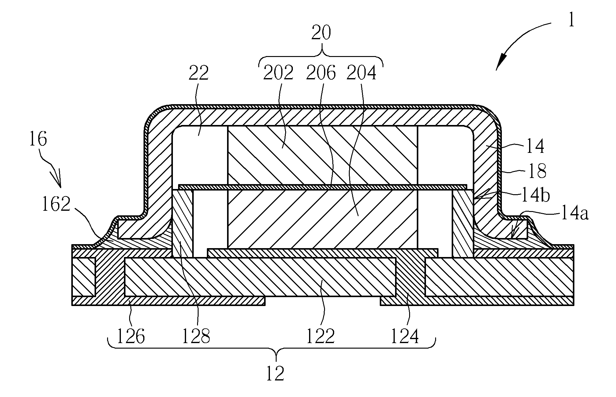
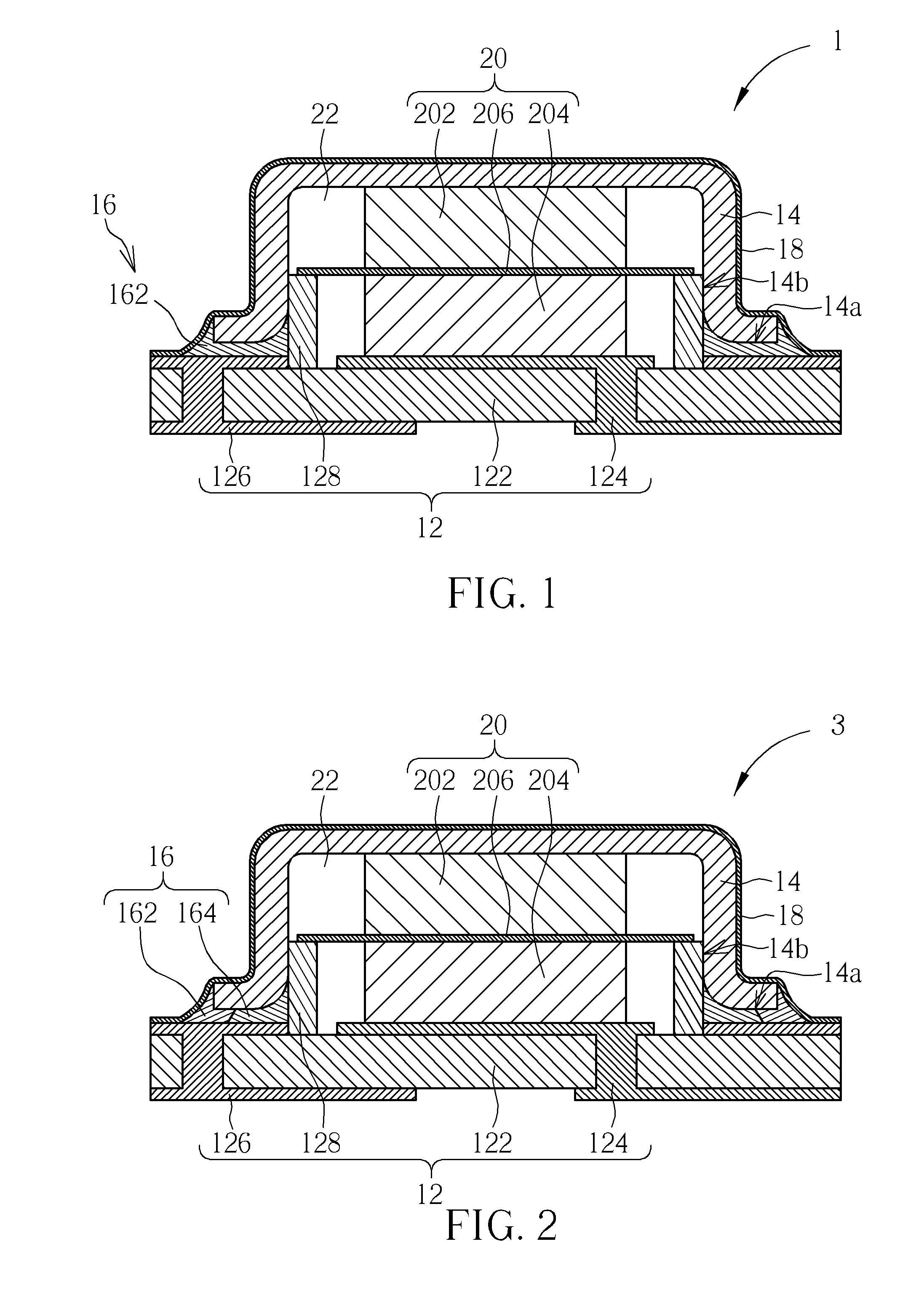
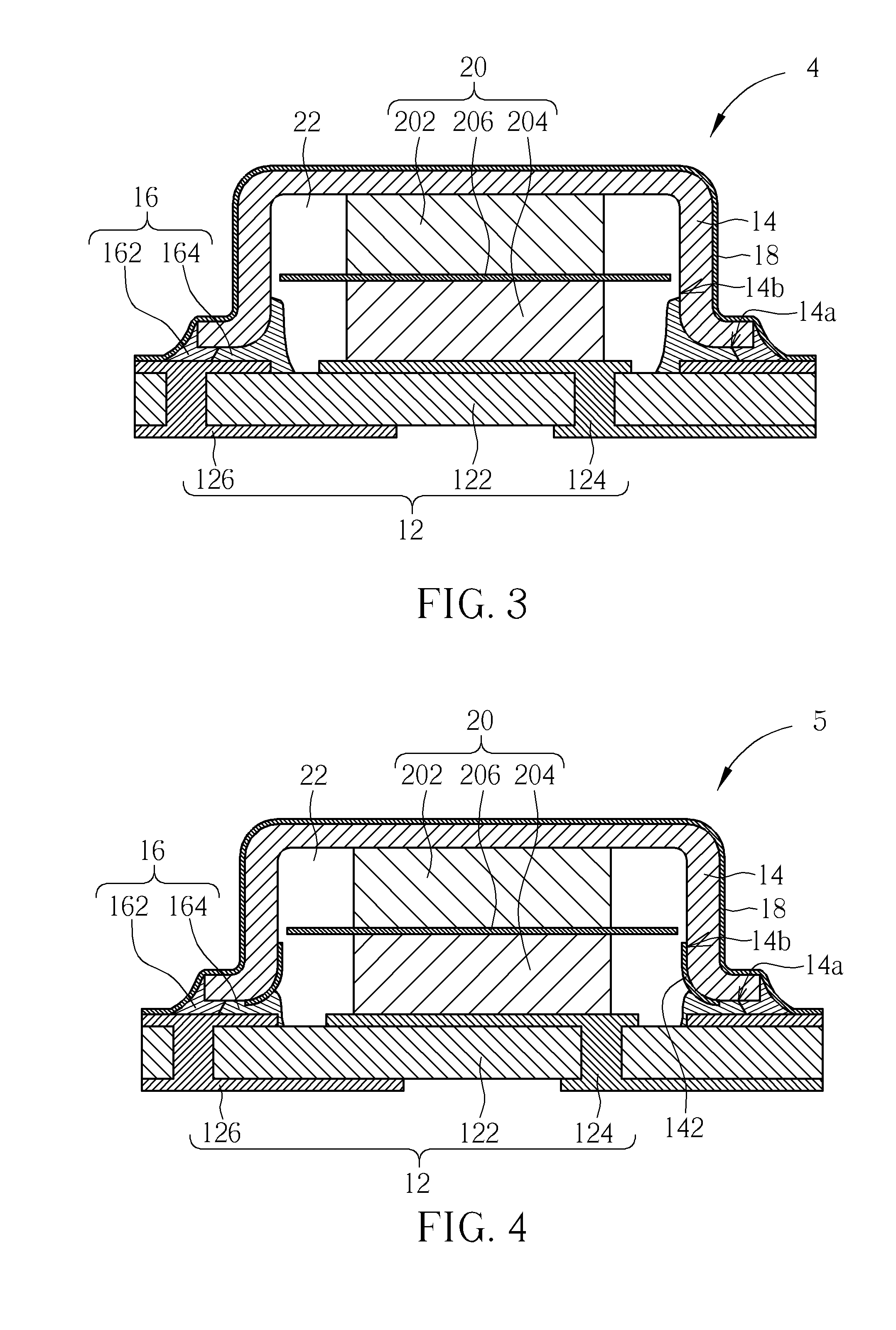
[0025]Please refer to FIG. 1, which is a sectional view of an energy storage device 1 of an embodiment according to the invention. The top-view profile of the energy storage device 1 can be a rectangle or other closed shape profile, which will not be described hereafter. In the embodiment, the energy storage device 1 includes a circuit board 12, a conductive cover 14, a sealing structure 16, a metal coating layer 18, and an electrochemical cell 20. The conductive cover 14 is disposed on the circuit board 12 and sealed by the sealing structure 16. The electrochemical cell 20 is disposed therein. The metal coating layer 18 covers the conductive cover 14, the sealing structure 16, and the circuit board 12 for structurally stabilizing the sealing structure 16. Therefore, even if the energy storage device 1 needs to be heated, the energy storage device 1 still can be maintained in structural integrity, stability, and sealability and can function normally.

[0026]For further details, in the...


PUM

PropertyMeasurementUnit
Temperatureaaaaaaaaaa
Electrical conductoraaaaaaaaaa

Abstract

An energy storage device and a method of manufacturing the same are disclosed. The energy storage device includes a circuit board, a conductive cover disposed above the circuit board, a sealing structure, a metal coating layer, and an electrochemical cell. The sealing structure is disposed between the circuit board and the circumference of the conductive cover such that the circuit board, the conductive cover, and the sealing structure together form a sealed space where the electrochemical cell is disposed. The metal coating layer continuously covers a part of the conductive cover, an exposed portion of the sealing structure, and a part of the circuit board. Therefore, even if the energy storage device needs to be heated during a product assembly, the metal coating layer can keep the sealing structure structurally stable, and the electrolyte of the electrochemical cell will not leak; the whole energy storage device therefore can keeps undamaged.

Description

CROSS REFERENCE TO RELATED APPLICATIONS[0001]This application claims the benefit of U.S. Provisional Application No. 61 / 475,237, which was filed on Apr. 14, 2011 and is incorporated herein by reference.BACKGROUND OF THE INVENTION[0002]1. Field of the Invention[0003]The invention relates to an energy storage device and a method of manufacturing the same, and especially relates to an energy storage device of electrochemical cell and a method of manufacturing the same.[0004]2. Description of the Prior Art[0005]The demand of portable electronic products (such as hand phone, tablet computer and so on) to energy storage device (such as secondary battery or electric double-layer capacitor) is not merely for being high energy density and light weight. As the size and the production difficulty of electronic products are required to be reduced, the above demand is also for being small-sized and being capable of being welded on a printed circuit board by surface mount technique (SMT) so as to ...

Claims


Application Information

Patent Timeline
IPC IPC(8): H01M2/00H05K5/00H01M10/04H01M50/105H01M50/184H01M50/186H01M50/191
CPCH01M2/08H01G11/74H01G11/82Y10T29/43H01M2/0202H01M10/4257Y10T29/4911H01G2/06Y02E60/10Y02P70/50H01M50/184H01M50/105H01M50/186H01M50/191Y02E60/13
Inventor WANG, CHUNG-HSIUNGLIN, CHI-FENGCHUNG, HAN-YANGLIAO, WEN-HSIUNG
Owner CYNTEC
Why Eureka
Try Eureka