Joining apparatus and method of joining

Inactive Publication Date: 2020-01-02
HONDA MOTOR CO LTD
View PDF0 Cites 0 Cited by
  • Summary
  • Abstract
  • Description
  • Claims
  • Application Information

AI Technical Summary

Benefits of technology

The present invention is a joining apparatus and method that can favorably join two metal members using electrification and pressurization. The apparatus includes an electrifying / pressurizing head with an abutting surface that contacts the pressure-receiving surface of the first metal member. An insulating section is provided at a certain position in the abutting surface, which can lengthen the distance from the electrode section to an adjacent region closest to the pressure-receiving surface. This prevents excessive heating of the adjacent region and avoids variation in heat generation, resulting in favorable joining of the two metal members.

Problems solved by technology

If, as a result, variation occurs in the generated heat amount of the joining interface, then sometimes it will be difficult for the first metal member and the second metal member to be favorably joined.

Method used


Image

  • Joining apparatus and method of joining
  • Joining apparatus and method of joining
  • Joining apparatus and method of joining

Examples


Embodiment Construction

[0021]A preferred embodiment of a joining apparatus and a method of joining according to the present invention will be presented and described in detail with reference to the accompanying drawings. Note that in the drawings below, configuration elements displaying the same or similar functions and advantages will be assigned with the same reference symbols, and repeated descriptions thereof will sometimes be omitted.

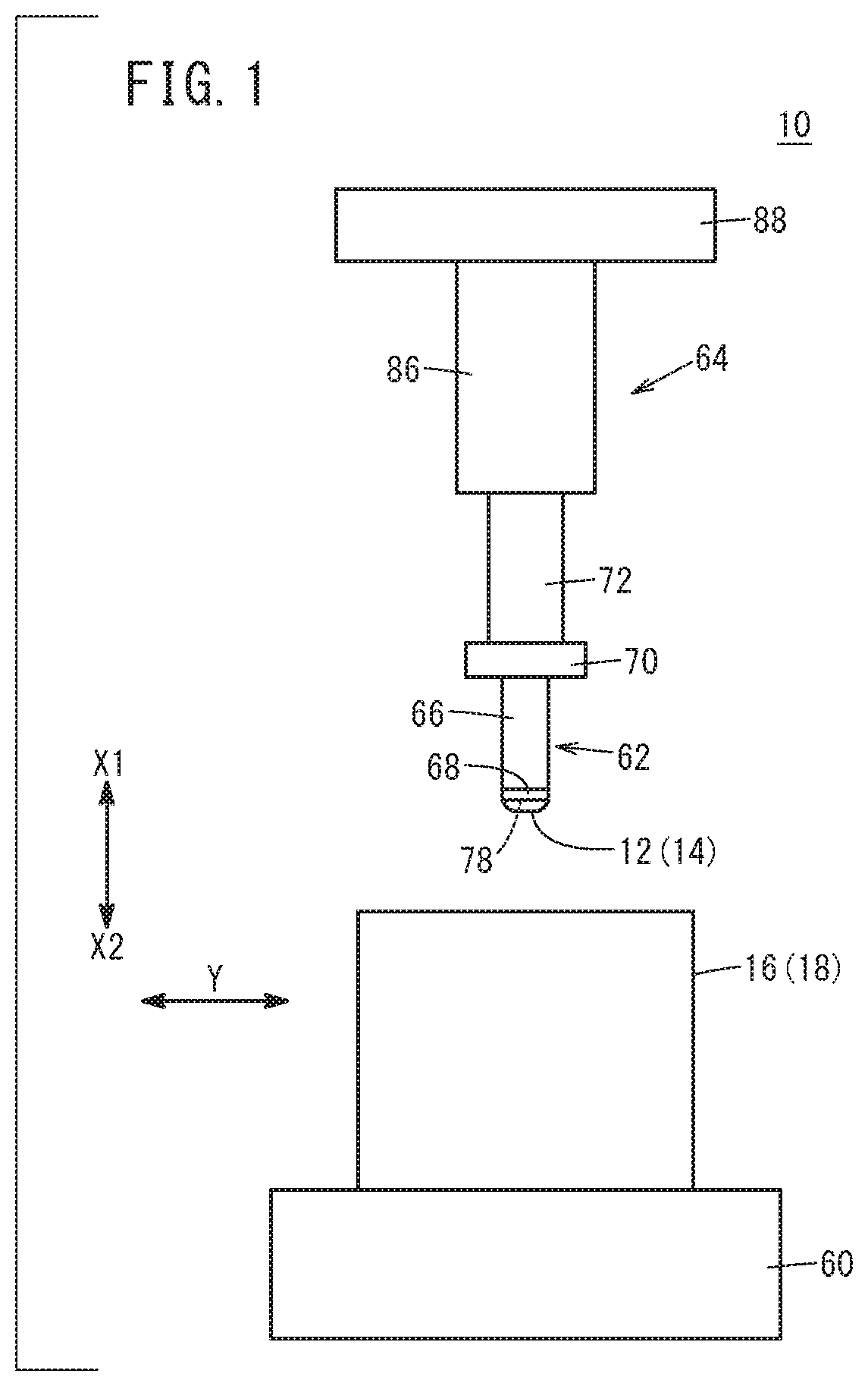
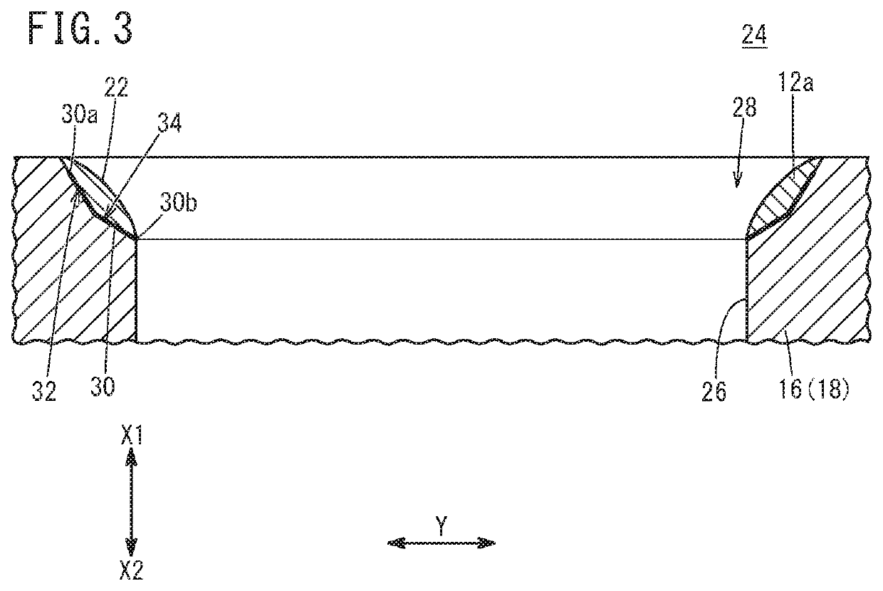
[0022]Described below is an example where, by applying a joining apparatus 10 according to the present embodiment shown in FIG. 1, a first metal member 14 being a work (hereafter, also called a “valve seat material 12”) eventually processed into a valve seat 12a (refer to FIG. 3) and a second metal member 18 being a cylinder head main body 16 are joined to obtain a joined body 20 (refer to FIG. 9). By, for example, performing machining, and so on, using the likes of an unillustrated cutting apparatus, on the joined body 20 obtained using the joining apparatus 10 and, as ...


PUM

PropertyMeasurementUnit
Pressureaaaaaaaaaa
Diameteraaaaaaaaaa
Distanceaaaaaaaaaa

Abstract

A joining apparatus includes an electrifying / pressurizing head provided with an abutting surface contacting a pressure-receiving surface of a first metal member, joins the first metal member and a second metal member by electrification and pressurization employing the electrifying / pressurizing head, and obtains a joined body in which a joining interface inclines with respect to the pressure-receiving surface. The abutting surface includes: an electrode section capable of electrifying the first metal member; and an insulating section configured from an insulating material. At least a shortest portion where a distance from the joining interface will be shortest, of the pressure-receiving surface will be a non-contact-with-electrode section of non-contact with the electrode section, and the insulating section contacts at least part of the non-contact-with-electrode section.

Description

CROSS-REFERENCE TO RELATED APPLICATION[0001]This application is based upon and claims the benefit of priority from Japanese Patent Application No. 2018-124844 filed on Jun. 29, 2018, the contents of which are incorporated herein by reference.BACKGROUND OF THE INVENTIONField of the Invention[0002]The present invention relates to a joining apparatus and a method of joining that join a first metal member and a second metal member by electrification and pressurization.Description of the Related Art[0003]For example, Japanese Laid-Open Patent Publication No. 11-090621 discloses a joining apparatus that, when joining a first metal member and a second metal member by performing electrification and pressurization between two electrodes, brings an abutting surface of one of the electrodes into contact with a pressure-receiving surface of the first metal member. In a joined body eventually obtained by this joining apparatus, a planar direction of a joining interface of the first metal member ...

Claims


Application Information

Patent Timeline
IPC IPC(8): B23K11/11B23K11/25
CPCB23K11/25B23K11/11B23K11/02B23K11/3009
Inventor YAMAZAKI, TAKESHITASHIRO, TAKAHISANAGAI, HIROYUKIYOKOYAMA, TAKEFUMI
Owner HONDA MOTOR CO LTD
Why Eureka
Try Eureka