Rotating a long vessel

a technology of rotating vessels and long objects, which is applied in the direction of lifting devices, transportation and packaging, construction, etc., can solve the problems of large-diameter, generally heavy-lift objects, long and complex process, and significant negative impact on the overall scheduling, cost and safety of utilizing a two-crane lifting method

Active Publication Date: 2020-01-02
DURALI SYST DESIGN & AUTOMATION CO +1
View PDF3 Cites 4 Cited by
  • Summary
  • Abstract
  • Description
  • Claims
  • Application Information

AI Technical Summary

Benefits of technology

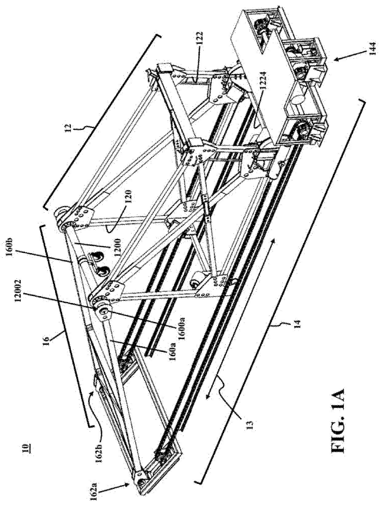
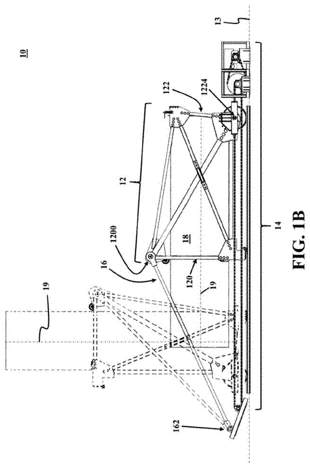
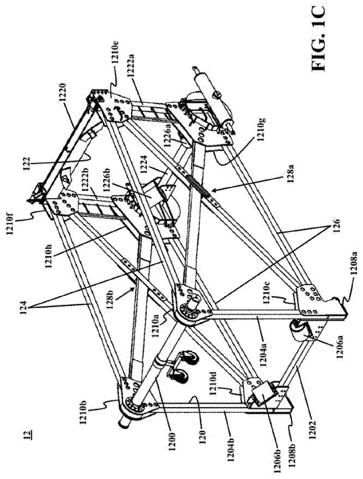
[0026]According to one or more exemplary embodiments, the present disclosure is directed to a method for rotating a vessel. An exemplary method may include placing the vessel or a portion of the vessel within a container assembly, the container assembly comprising a head end frame and a tail end frame, the head end frame and the tail end frame interconnected utilizing a plurality of side frame members, restraining translational and rotational movements of the vessel relative to the container assembly, actuating a linear movement of a bottom edge of the tail end frame along a first axis, the first axis perpendicular to a main axis of the bottom edge, and rotating a top edge of the head end frame about the main axis of the bottom edge responsive to the linear movement of the bottom edge of the tail end frame along the first axis.

Problems solved by technology

Manufacturing and installing such long, large-diameter, and generally heavy-lift objects involves lengthy and complex processes.
However, this off-site prefabrication and on-site installation may lead to much more frequent use of transportation and lifting machinery, such as cranes.
Moreover, other problems such as swinging movements of an object and booms tip collision may have a significant negative impact on the overall scheduling, cost, and safety of utilizing a two-crane lifting method.
A significant issue with utilizing a two-crane method or approach is that the proper coordination between the two cranes depends heavily on skills of human operators and therefore has a significant impact due to human errors, which may be reduced but are not entirely unavoidable.
Furthermore, conventional mobile cranes may not be utilized in confined spaces, such as within tunnels.
However, the exemplary systems and methods may allow for rotating a long vessel in confined spaces due to low profiles of the exemplary systems.

Method used


Image

  • Rotating a long vessel
  • Rotating a long vessel
  • Rotating a long vessel

Examples


Embodiment Construction

[0047]In the following detailed description, numerous specific details are set forth by way of examples to provide a thorough understanding of the relevant teachings related to the exemplary embodiments. However, it should be apparent that the present teachings may be practiced without such details. In other instances, well-known methods, procedures, components, and / or circuitry have been described at a relatively high-level, without detail, in order to avoid unnecessarily obscuring aspects of the present teachings.

[0048]The following detailed description is presented to enable a person skilled in the art to make and use the methods and devices disclosed in exemplary embodiments of the present disclosure. For purposes of explanation, specific nomenclature is set forth to provide a thorough understanding of the present disclosure. However, it will be apparent to one skilled in the art that these specific details are not required to practice the disclosed exemplary embodiments. Descri...


PUM


Abstract

A system for rotating a vessel may include a container assembly. An exemplary container assembly may include a head end frame that may be spaced apart from and interconnected with a tail end frame. An exemplary container assembly may be configured to encompass and hold the vessel or a portion of the vessel. An exemplary system for rotating a vessel may further include a linear actuating mechanism that may be coupled to a bottom edge of the tail end frame. An exemplary linear actuating mechanism may be configured to drive a translational movement of the bottom edge of the tail end frame along a first axis. An exemplary system for rotating a vessel may further include a double-pivot link that may be pivotally connected between a top edge of the head end frame and a fixed revolute joint. An exemplary double-pivot link may be configured to rotate the top edge about the fixed revolute joint responsive to the translational movement of the bottom edge of the tail end frame along the first axis.

Description

CROSS-REFERENCE TO RELATED APPLICATION[0001]This application claims the benefit of priority from pending U.S. Provisional Patent Application Ser. No. 62 / 698,986, filed on Jul. 17, 2018, and entitled “LARGE-DIAMETER PIPE TURNOVER MACHINE,” which is incorporated herein by reference in its entirety.TECHNICAL FIELD[0002]The present disclosure relates to systems and methods for rotating long objects such as vessels and pipe sections, and particularly relates to systems and methods for rotating heavy-lift objects into an upright position.BACKGROUND[0003]Long and large-diameter objects such as pipes, process vessels, and reactors are frequently used in industrial projects, including in oil and gas industries and hydropower plants. Manufacturing and installing such long, large-diameter, and generally heavy-lift objects involves lengthy and complex processes. Different strategies are utilized in industrial projects to simplify manufacturing and installation of the aforementioned objects, suc...

Claims


Application Information

Patent Timeline
Patent Type & Authority Applications(United States)
IPC IPC(8): E04H12/34E21B19/15
CPCE21B19/155E04H12/345B66C1/42B66F11/00
Inventor MOUSAVI, SEYD HOSSEINJAMALIMEHR, AMINHOSSEINIMEHR, MOHAMMADALIABBASI BAHARANCHI, ALITORABI GOODARZI, ASHKANHASHEMI, SAEEDFADAKAR KOURKAH, FARSHADDURALI, MOHAMMAD
Owner DURALI SYST DESIGN & AUTOMATION CO
Why Eureka
Try Eureka