
Portable gas analysis device with compact measurement device

Active Publication Date: 2020-01-02
BENTEKK GMBH
View PDF0 Cites 1 Cited by
  • Summary
  • Abstract
  • Description
  • Claims
  • Application Information

AI Technical Summary

Benefits of technology

The invention is a new and improved gas measuring device that has several technical advantages over previous solutions. It is compact, durable, and can withstand difficult conditions. It provides better results even at extreme temperatures, and is safe for use in potentially dangerous environments. It is also more user-friendly and easy to calibrate and analyze data from multiple devices. Overall, this new invention is a more robust and reliable tool for measuring gas.

Problems solved by technology

At higher temperatures and pressures, the method accelerates, wherein there is a limit in each case of the load for the column and also the performance capacity of heater and fans.
Uneven temperatures in the course of the column or varying temperatures and pressures in the course of the measurement distort the measurement result and make it more difficult to compare various measurements.
The power supply from the grid permits heating to be performed inefficiently.
They are hardly usable outside a laboratory.
They are unsuitable for portable use.
In comparison to laboratory devices, these miniaturized gas chromatographs represent a compromise between performance capacity of the measurement and dimensions.
In many of these applications, the device also has to function in the case of extreme external temperatures, is only supplied with power via a battery, and is subjected to stresses due to shaking and impacts.

Method used


Image

  • Portable gas analysis device with compact measurement device
  • Portable gas analysis device with compact measurement device
  • Portable gas analysis device with compact measurement device

Examples


Embodiment Construction

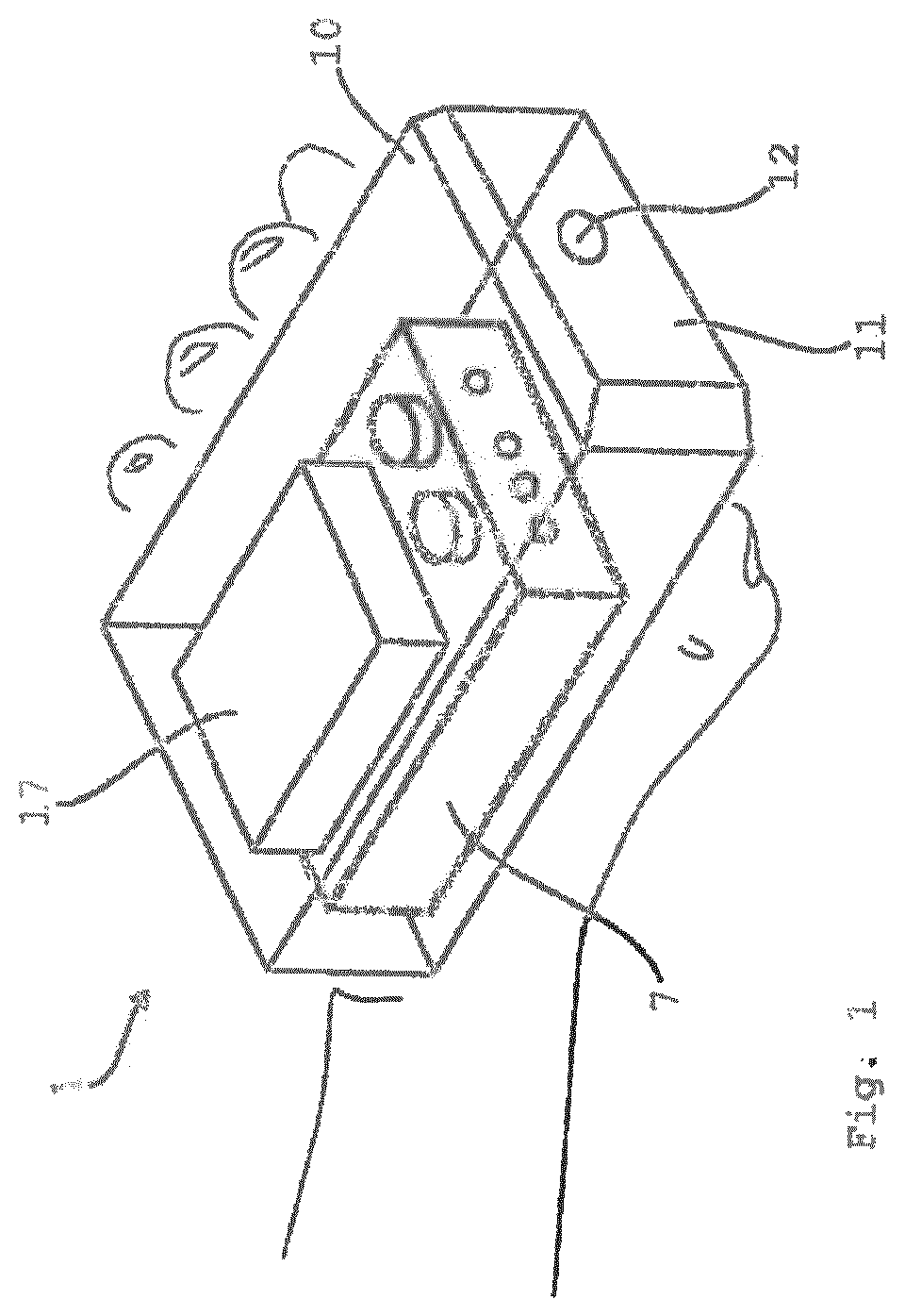
[0039]A portable gas analysis device identified in its entirety with the reference sign 1 has a housing 10, on the end face 11 of which an inlet 12 for a sample gas supply is arranged. A measuring unit 7 and an electrical energy accumulator 17 are arranged in the interior of the housing 10.

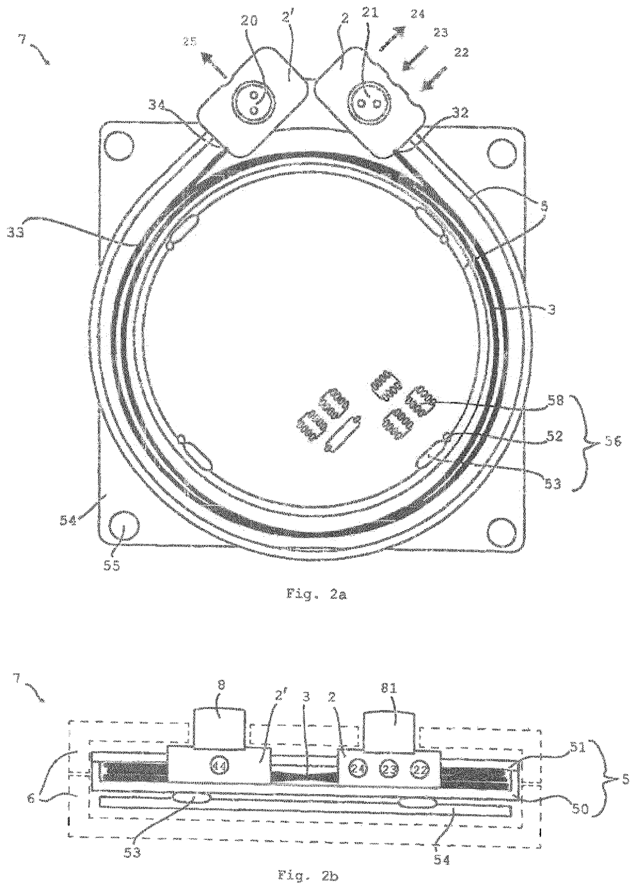
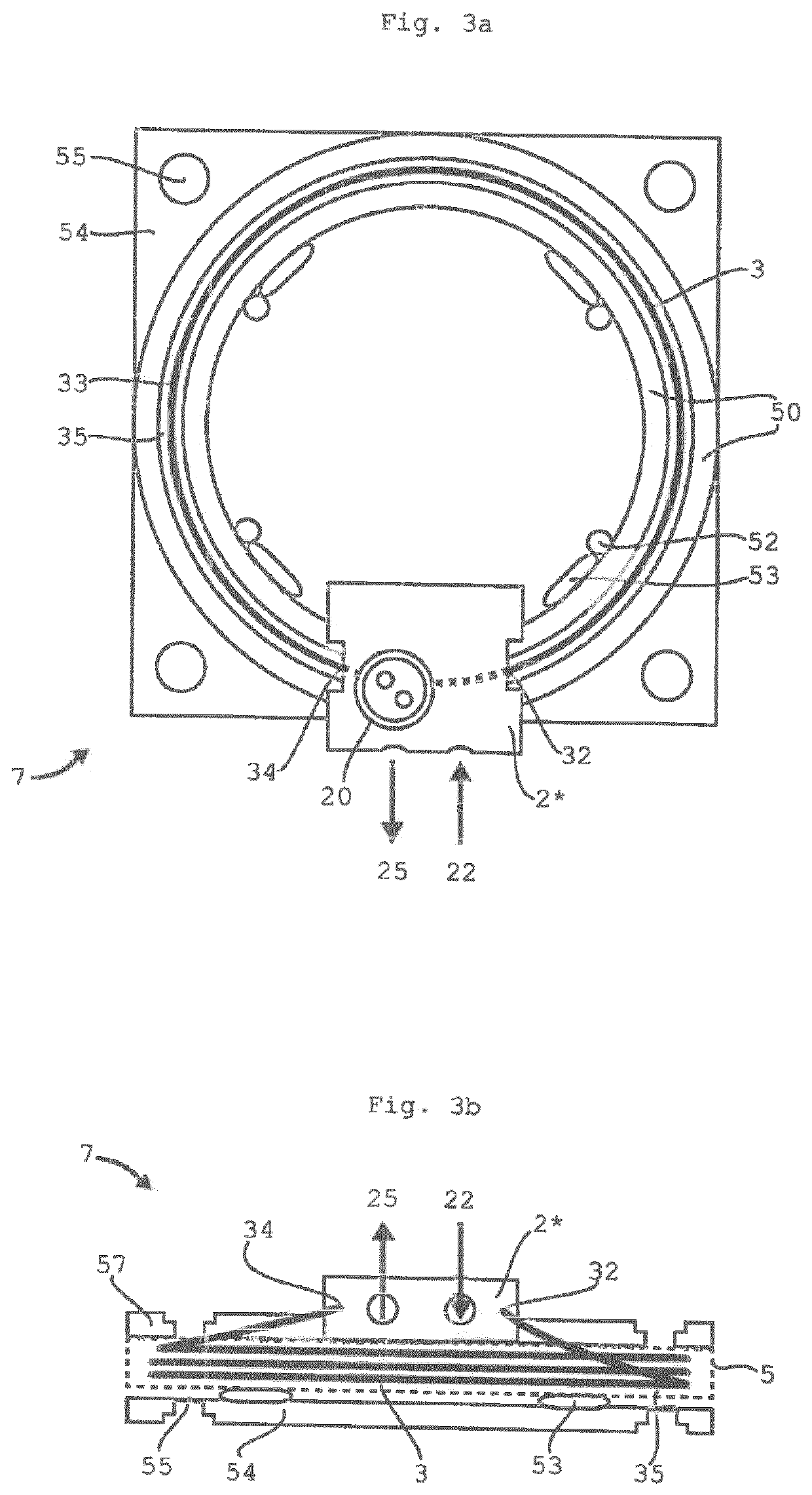
[0040]The measuring unit 7 comprises a separation column 3 (see FIGS. 2a, b) and a detector 8 and an optional seeker detector 81. Multiple openings are arranged on an end face of the measuring unit 7, which are used for the supply or exhaust, respectively, of sample gas and / or carrier gas, as will be explained in greater detail hereafter. The gas lines per se are not shown for reasons of comprehensibility.

[0041]To illustrate the size ratios, in FIG. 1 the exemplary embodiment of the portable gas analysis device 1 is illustrated in relation to the hand of a user.

[0042]Reference is now made to FIGS. 2a, b and the first exemplary embodiment of the invention illustrated therein. In this embodiment, a ...


PUM


Abstract

A portable gas analysis device having a separating column and a detector. The separating column is composed as a multi-capillary unit from parallel individual capillaries and, depending on the length, is bent into a compact shape, preferably even wound into multiple turns. A thermally conductive casing and a thermal stabilizing device are provided for the multi-capillary unit. The thermal stabilizing device comprises a temperature sensor, a heating element and control electronics. The casing protects the sensitive multi-capillary unit from mechanical actions; it acts as a protective space. The temperature-controlled casing also forms a space in which uniform and controlled conditions prevail and which in particular is isolated from the temperature and humidity of the environment, allowing reliable measurements outside a laboratory environment, in the field. This double effect of the casing for the capillaries in conjunction with the compact dimensions forms the true essence of the invention.

Description

CROSS-REFERENCE TO RELATED APPLICATIONS[0001]This application is a U.S. national stage patent application of International Patent Application No. PCT / EP2017 / 076235, filed Oct. 13, 2017, which claims the priority of DE 10 2017 201 677.9, filed on Feb. 2, 2017, the entire contents of each of which are incorporated herein by reference.FIELD OF THE INVENTION[0002]The invention relates to a portable gas analysis device having a measuring unit comprising a separation column and a detector.BACKGROUND OF THE INVENTION[0003]Gas chromatography is an established measuring method to determine the chemical composition and concentration of volatile materials. In the method, a gas mixture is injected into a column, in which there is a pressure gradient and thus gas flow toward the end, wherein each material propagates at a separate speed in the column and reaches the end of the column after a specific retention time. A signal for the intensity according to retention time, the so-called chromatogra...

Claims


Application Information

Patent Timeline
IPC IPC(8): G01N30/60G01N30/54G01N30/30G01N30/62
CPCG01N30/6043G01N30/62G01N30/6095G01N30/30G01N30/54G01N2030/0095G01N2030/025
Inventor SCHMITTMANN, MATTHIASWEBER, JOHANNESWEBERJÜNEMANN, ARNE
Owner BENTEKK GMBH
Learn More