
Cable strand for activating ejection valves

a technology of ejection valve and cable strand, which is applied in the direction of transmission, coupling device, electrical apparatus, etc., can solve the problems of requiring considerable cost and both possibilities have considerable drawbacks, and achieve the effect of removing undeired interference radiation

Active Publication Date: 2007-10-11
MAN TRUCK & BUS AG
View PDF7 Cites 0 Cited by
  • Summary
  • Abstract
  • Description
  • Claims
  • Application Information

AI Technical Summary

Benefits of technology

[0022]To achieve a resistance of the cable strand to media that is as free of gaps as possible, it is advantageous to provide the filters and filter supports with an electrically insulating media-resistant sheathing prior to the molding or foaming
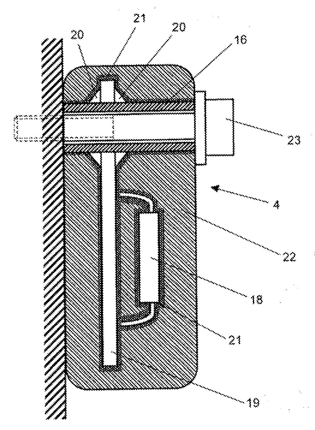
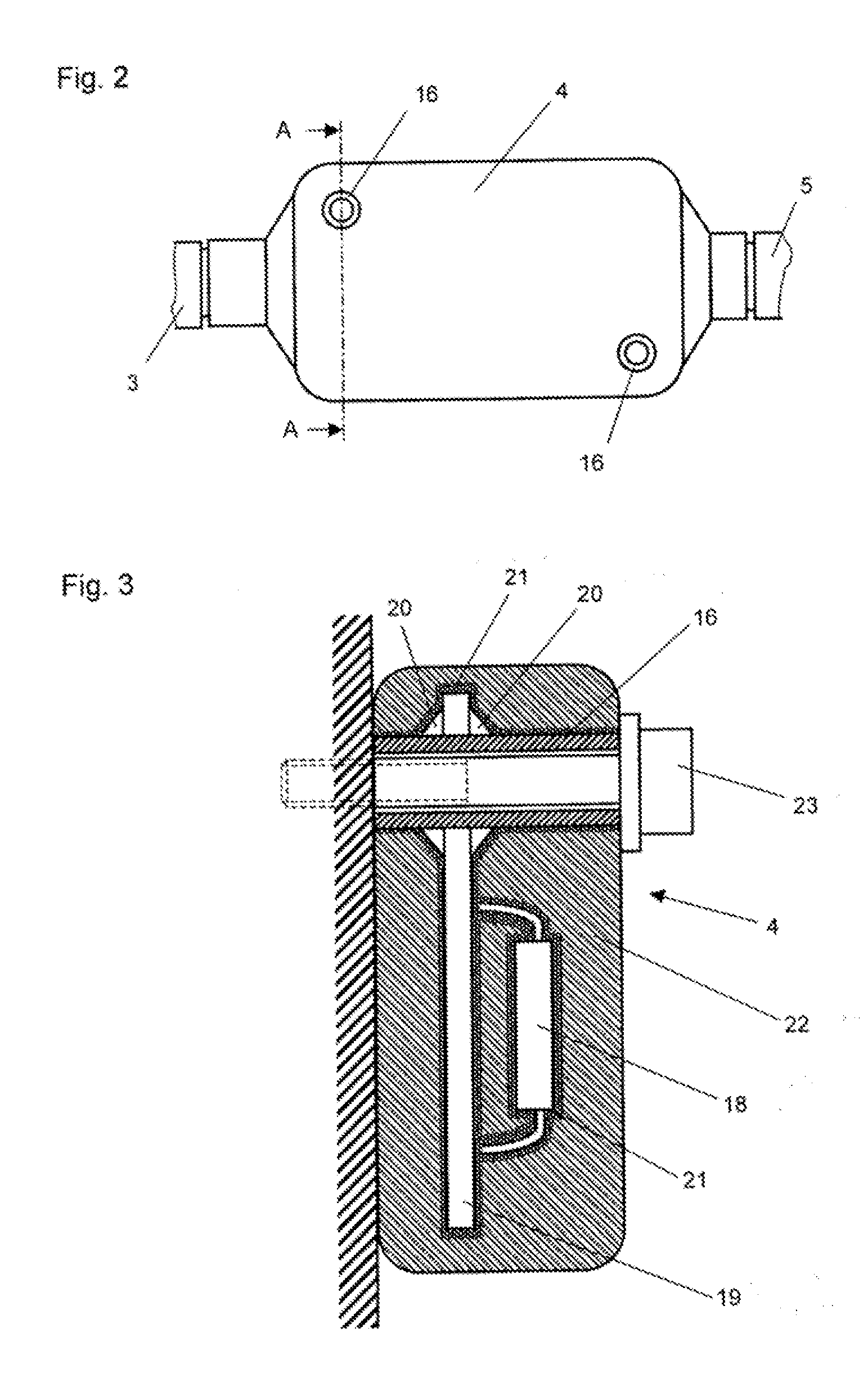
[0023]It is also advantageous to mold or foam the filter support, with the components disposed thereon, with a sealing compound or filler so that the components are supported relative to one another and relative to the filter support in a low-vibration manner. As a result, failure of, for example, component connections that is induced by vibrations is prevented. To protect against mechanical influences, the filter support, together with the cable strand, are foamed or molded in a mechanically configuration-giving manner, for example with polymeric material, whereby the thus-produced envelope advantageously ensures the mechanical protection in the manner of a housing or casing.
[0024]To produce the necessary ground connection between the filter circuits on the filter support and on the engine control device, it is advantageous to dispose the filter support in the immediate vicinity of the engine control device, or ideally on the housing of the engine control device.

Problems solved by technology

Due to the short switching or actuation cycles, with their steep signal amplitudes, and the considerable actuation currents that occur with common-rail injection systems, high-frequency actuation peaks result that, as interference radiation, are irradiated from the line connections between the engine control system and the injection valves.
Both possibilities have considerable drawbacks for use in commercial vehicles, especially those that are produced only in a small scale series for special applications.
A modification of the engine control system would also require considerable expense, assuming these measures would even be possible due to technical conditions, such as available space in the housing of the engine control system, the development of heat etc.

Method used


Image

  • Cable strand for activating ejection valves
  • Cable strand for activating ejection valves
  • Cable strand for activating ejection valves

Examples


Embodiment Construction

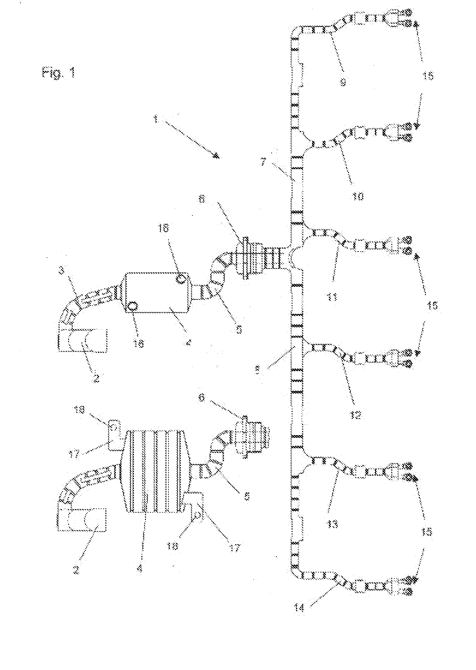
[0027]Referring now to the drawings in detail, FIG. 1 shows a cable strand 1 that is provided at one end with a plug connector 2 for connection to an engine control device. Proceeding from the plug connector 2, the cable strand 1 leads, via a first section 3, to a filter module 4, and from there, via a second section 5, further to a lead-through flange 6. The purpose of the lead-through flange 6 is to guide the cable strand 1 through the valve cover of the internal combustion engine (not illustrated) and to seal the passageway. Following the lead-through flange 6, the cable strand 1 splits into two partial strands 7, 8, from which feed lines 9-14 branch off to the injection valves of the internal combustion engine (not illustrated). Each of the feed lines 9-14 is comprised of two lines, the ends of which are provided with connecting eyelets 15, via which, in the installed state, the lines are connected with the electrical connections of the injection valves.

[0028]The cable strand 1 ...


PUM


Abstract

A cable strand for the activation of electrically actuatable injection valves of internal combustion engines having a common-rail injection system, wherein the cable strand connects an engine control device with the injection valves. Electrical cables of the cable strand are molded and / or foamed in a carrier that largely prescribes the shape of the cable strand. At least one filter is also molded and / or foamed in the cable strand and is adapted to affect the electromagnetic compatibility of the cable strand arrangement.

Description

[0001]The instant application should be granted the priority date of Mar. 24, 2006, the filing date of the corresponding German patent application 10 2006 013 543.1BACKGROUND OF THE INVENTION[0002]The present application relates to a cable strand for the activation of electrically actuatable injection valves of internal combustion engines having a common-rail injection system, wherein the cable strand connects an engine control device with the injection valves, and wherein electrical cables of the cable strand are molded and / or foamed in a carrier that to a large extent prescribes the shape of the cable strand.[0003]With modern self-ignition or compression ignition internal combustion engines, especially those used in commercial vehicles, increasingly fuel injection systems of the common-rail type are used. The advantage of such systems is that the pressurization is entirely decoupled from the injection process, as a result of which a plurality of partial injections can take place i...

Claims


Application Information

Patent Timeline
Patent Type & Authority Applications(United States)
IPC IPC(8): H03H7/00
CPCB60R16/0207F02M51/005F02D41/3005F02D41/20
Inventor KALASS, RAINERHARRES, ULRICH
Owner MAN TRUCK & BUS AG
Learn More