
Switching device for electronic musical instrument

a technology of electronic musical instruments and switching devices, applied in the direction of instruments, electrotrophonic musical instruments, etc., can solve the problems of sound generation defects, sound generation defects easily occurring, and above-described problems, and achieve the effect of stably generating sound

Active Publication Date: 2020-01-02
YAMAHA CORP
View PDF0 Cites 4 Cited by
  • Summary
  • Abstract
  • Description
  • Claims
  • Application Information

AI Technical Summary

Benefits of technology

The patent text describes how an electronic musical instrument can generate sound that is stable and effective. This means that the instrument can produce good-quality music without experiencing any problems or issues while performing.

Problems solved by technology

In such a case, the sensor does not operate stably, and there is a risk that a sound generation defect may occur.
Further, in a keyboard device in which a hammer does not press a sensor (or a keyboard device in which a hammer is not used), there is a risk that the above-described problem will occur even in a case where a key directly presses a sensor, so this sound generation defect easily occurs.
Further, there is a risk that the above-described problem will occur also in other electronic musical instruments.

Method used


Image

  • Switching device for electronic musical instrument
  • Switching device for electronic musical instrument
  • Switching device for electronic musical instrument

Examples


first embodiment

1-1. Configuration of Keyboard Device

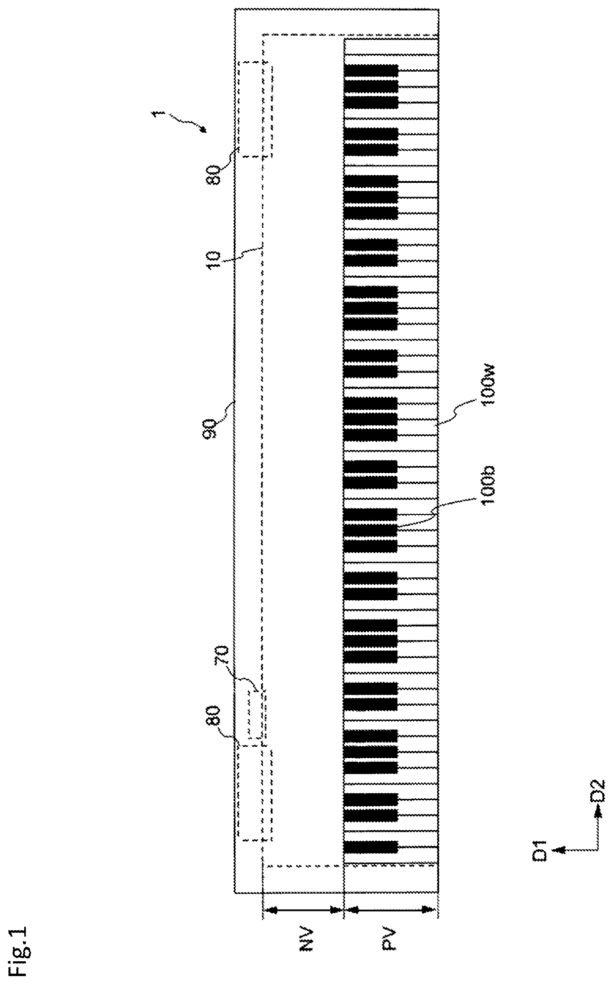
[0039]FIG. 1 shows the configuration of a keyboard device in a first embodiment. In this example, a keyboard device 1 is an electronic keyboard musical instrument such as an electronic piano that generates sound according to key pressing by a user (a player). Note that the keyboard device 1 may also be a keyboard-type controller that outputs control data (for example, MIDI) for controlling an external sound source device according to key pressing. In this case, the keyboard device 1 may not be provided with a sound source device.

[0040]The keyboard device 1 includes a keyboard assembly 10. The keyboard assembly 10 includes white keys 100w and black keys 100b. A plurality of the white keys 100w and the black keys 100b are arranged side by side. The number of keys 100 is N, which is 88 in this example. The direction in which the keys 100 are arranged is referred to as a scale direction (or may be referred to as a direction D2). When the white keys 1...

second embodiment

2. Configuration of Circuit Board

[0075]In the second embodiment, a circuit board 360a having a shape different from that in the first embodiment will be described.

[0076]FIG. 13 is a top view showing a partial extraction of the keyboard device 1. As shown in FIG. 13, in the keyboard device 1, a black key 100b-1 and a black key 100b-2 are respectively arranged among a white key 100w-1, a white key 100w-2 and a white key 100w-3, and thus the shape of each white key is different. Therefore, the direction of the force applied when the player presses is different for the white key 100w-1, the white key 100w-2 and the white key 100w-3. For example, the shape of the white key 100w-1 is symmetrical, so force is easily transmitted in the direction perpendicular to the key. On the other hand, the white key 100w-2 has a so-called L-shape in which the upper right portion is notched out. The white key 100w-3 has a shape that is symmetrical left-right with the white key 100w-2. Therefore, the whit...


PUM


Abstract

Provided is a switching device for an electronic musical instrument, comprising: a plurality of first electrodes that are adjacently arranged; a second electrode arranged between a pair of the plurality of first electrodes, and insulated from the plurality of first electrodes by a plurality of spaces; a rotatable actuator; and a conductive member configured to electrically connect the first electrodes and the second electrode according to rotation of the actuator. The plurality of spaces extend longitudinally in a first direction. The first direction is a direction between a rotational shaft direction of the actuator and a direction orthogonal to the rotational shaft direction.

Description

CROSS REFERENCE TO RELATED APPLICATIONS[0001]The present application is a continuation application of International Application No. PCT / JP2018 / 7480, filed Feb. 28, 2018, which claims a priority to Japanese Patent Application No. 2017-60142, filed Mar. 24, 2017. The contents of these applications are incorporated herein by reference in their entirety.FIELD OF INVENTION[0002]The present invention relates to a switching device for an electronic musical instrument and a switching device for a keyboard device.BACKGROUND[0003]In an acoustic piano, an action mechanism operates to convey a predetermined feeling (hereinafter referred to as a touch feeling) to a player's finger through a key. In the acoustic piano, the action mechanism is required to press a key with a hammer. On the other hand, in an electronic keyboard instrument, key pressing is detected by a sensor, so it is possible to generate sound without having an action mechanism like that in an acoustic piano. The touch feeling of ...

Claims


Application Information

Patent Timeline
Patent Type & Authority Applications(United States)
IPC IPC(8): G10H1/34
CPCG10H2220/221G10H1/346G10H1/0558G10H2220/275G10H2220/285
Inventor TANOUE, MICHIKO
Owner YAMAHA CORP
Features
  • Generate Ideas
  • Intellectual Property
  • Life Sciences
  • Materials
  • Tech Scout
  • Unparalleled Data Quality
  • Higher Quality Content
  • 60% Fewer Hallucinations
Learn More