Two-pole tefc electric motor and an electric motor drive arrangement

Inactive Publication Date: 2020-01-02
ABB (SCHWEIZ) AG
View PDF0 Cites 1 Cited by
  • Summary
  • Abstract
  • Description
  • Claims
  • Application Information

AI Technical Summary

Benefits of technology

[0011]The solutions provided by the present disclosure avoids the drawbacks of the conventional approaches. Particularly, a two-pole TEFC (totally enclosed, fan-cooled) electric motor with improved vibrations characteristics is achieved, without trading

Problems solved by technology

Improved vibration characteristics are achieved even for larger frame sizes, for which rigorous vibration

Method used


Image

  • Two-pole tefc electric motor and an electric motor drive arrangement

Examples


Example

[0015]According to a first aspect of the disclosure, a two-pole TEFC (totally enclosed, fan-cooled) electric motor is provided. Preferably, but not necessarily, the motor is an induction motor.

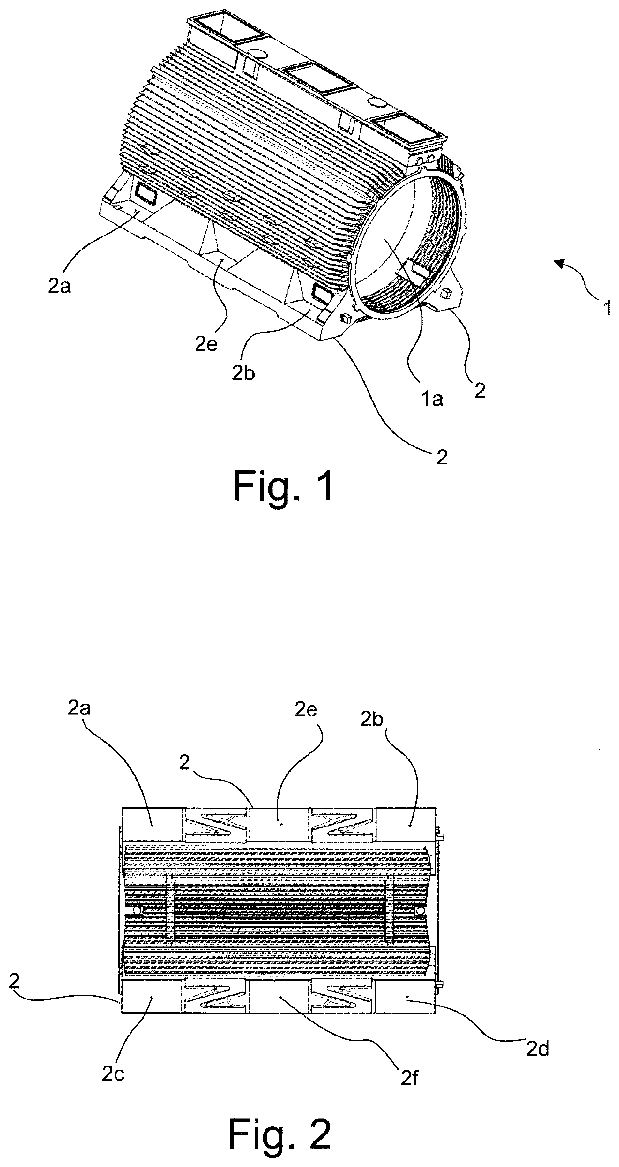
[0016]The motor comprises a housing 1 having an inner space 1a, a stator assembly arranged annularly within the inner space of the housing, a motor shaft rotatably supported so as to concentrically extend through the stator assembly, and a rotor assembly fixed to and surrounding the motor shaft within the inner space, the rotor assembly being disposed concentrically with and inside the stator assembly. Preferably, but not necessarily, the housing 1 is a cast housing, at least in part.

[0017]The motor further comprises a mounting foot structure 2 protruding radially from the outer surface of the housing 1 for mounting said motor to a planar base structure. The mounting foot structure 2 comprises four mounting points 2a, 2b, 2c, 2d defining corner points of a rectangular mounting footprint of the...


PUM


Abstract

A two-pole TEFC (totally enclosed, fan-cooled) electric motor is concerned. A housing of the motor as an inner space, into which a stator assembly, a motor shaft and a rotor assembly fixed to and surrounding the motor shaft is fitted. A mounting foot structure radially protrudes from the outer surface of the housing for mounting the induction motor to a planar base structure. The mounting foot structure includes four mounting points defining corner points of a rectangular mounting footprint of the motor, such that the rectangular mounting foot print has two opposite sides parallel with the motor shaft. Furthermore, the mounting foot structure including at least an additional mounting point positioned on each side of the mounting footprint parallel with the motor shaft, between the corner points of the mounting footprint.

Description

FIELD OF THE DISCLOSURE[0001]The present disclosure relates to electric two-pole electric motors. More particularly, the present disclosure concerns electric motors of the TEFC (totally enclosed, fan-cooled)-type. In addition, an electric motor drive arrangement is concerned.BACKGROUND OF THE DISCLOSURE[0002]Electric motors of the TEFC-type are well known and commonly used in a wide range of end-use applications. Particularly, such motors are enclosed so that surrounding air is not permitted to circulate within the motor housing, resulting in a robust structure. In order to provide sufficient cooling for such motors, an external fan, often provided on the motor shaft, is arranged to blow cooling air along the outer circumference of the motor housing, which is typically provided with cooling ribs. As excess heat is transferred through the motor housing, it is generally considered desirable to reserve as much of the motor housing's surface area for heat transfer as possible. Moreover,...

Claims


Application Information

Patent Timeline
IPC IPC(8): H02K5/24H02K5/18H02K9/06H02K11/33H02K17/04
CPCH02K5/24H02K17/04H02K2213/03H02K9/06H02K11/33H02K5/18H02K5/00H02K5/06H02K9/08
Inventor MATTILA, SIMOAARNIVUO, SAMUKOSONEN, JANI
Owner ABB (SCHWEIZ) AG
Why Eureka
Try Eureka