Methods and compositions for compression molding

Active Publication Date: 2020-01-16
ARRIS COMPOSITES INC
View PDF8 Cites 5 Cited by
  • Summary
  • Abstract
  • Description
  • Claims
  • Application Information

AI Technical Summary

Benefits of technology

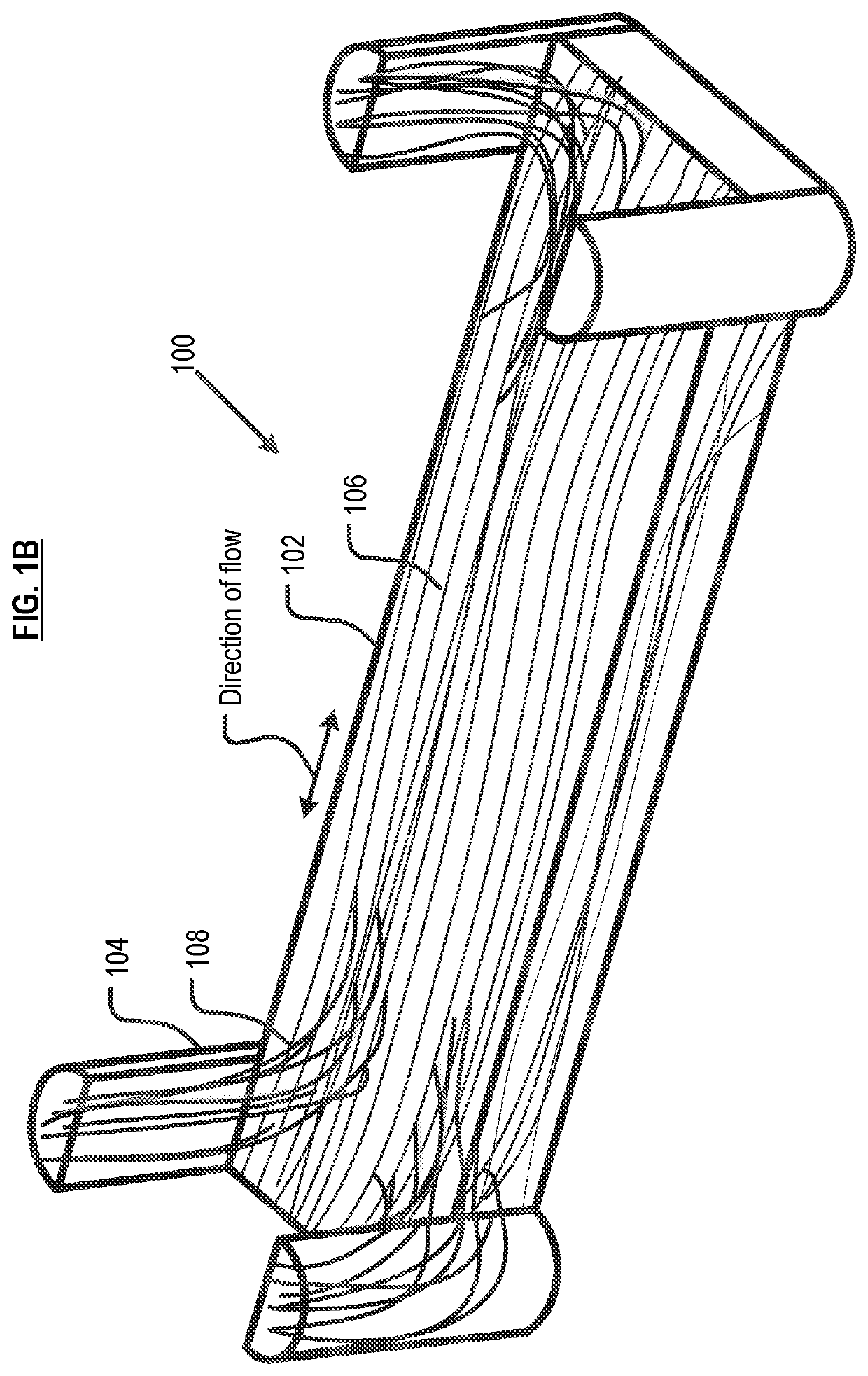
[0009]It was found that, as long as the flowing, continuous fibers are of sufficient length to extend beyond the confines of the cavity that they are filling, such flowing fibers entwine themselves with the non-flowing continuous fiber via overlap and, of course, the resin matrix itself. The flowing, continuous fibers tend to align with the direction of resin flow, which increases the strength and stiffness of small features.
[0010]The i

Problems solved by technology

The use of fiber-reinforced composites in compression molding presents certain challenges.
For example, the presence of voids compromises the strength of a part.
Moreover, it can be problematic to flow resin to portions of the mold having very

Method used


Image

  • Methods and compositions for compression molding
  • Methods and compositions for compression molding
  • Methods and compositions for compression molding

Examples


Embodiment Construction

[0073]Compression molding, well known in the art, utilizes a female mold and a male mold, applying heat and pressure to form a molded part. Relative to the prior art, methods described herein provide improvements in compression-molded parts comprising fiber composites.

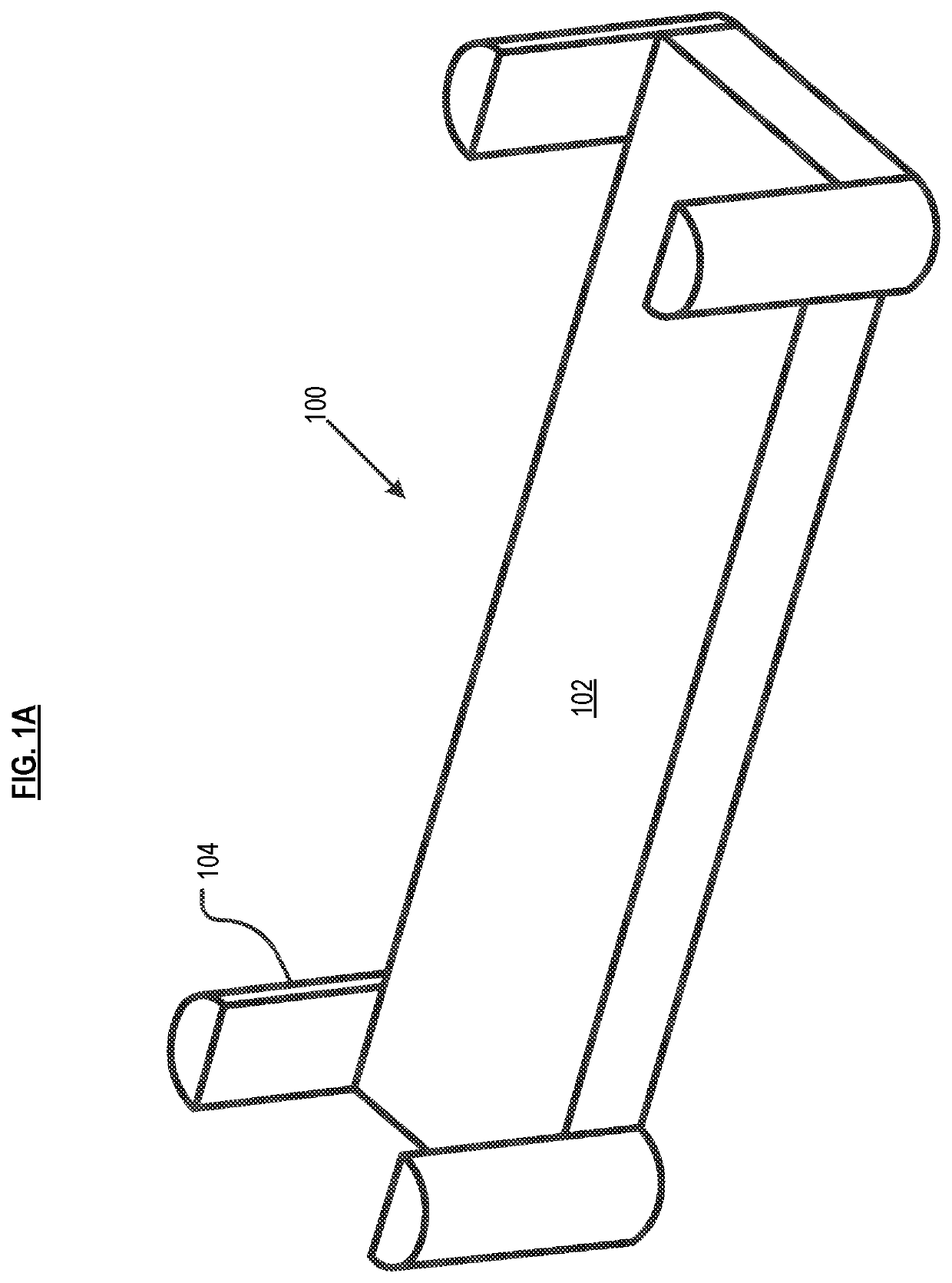
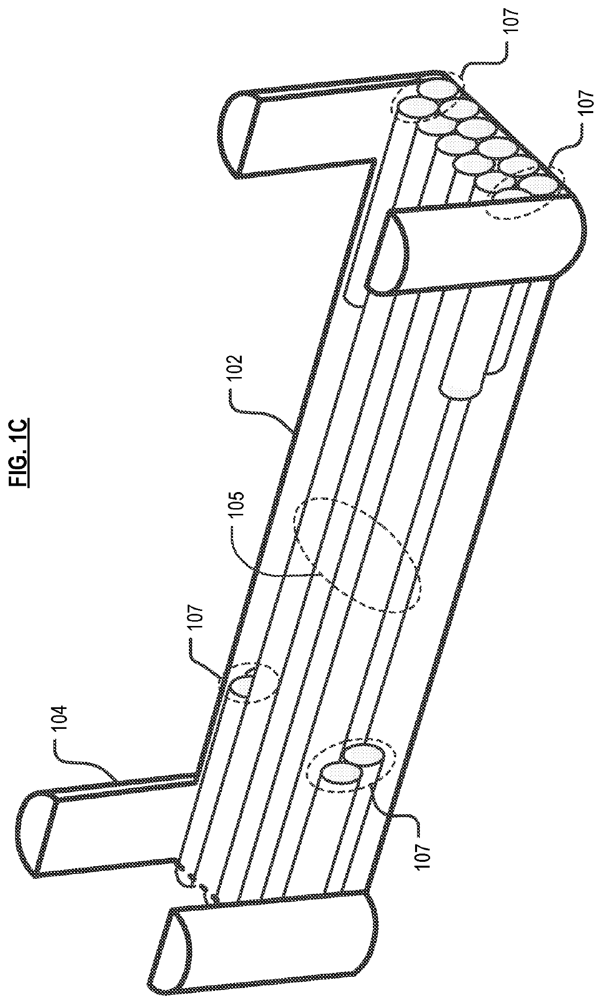
[0074]Referring now to FIG. 6, in method 600 in accordance with the invention, the volume and length of the flowing continuous fiber bundle(s) are determined in task S601. The length of a flowing continuous fiber bundle(s) is based on the length of the typically relatively smaller cavities / feature(s) (hereinafter “minor features”) that depend from the major features(s), plus the amount of overlap that is desired between the flowing fiber and the non-flowing fiber. In other words, the “overlap” is a measure of how far the flowing fibers will extend beyond the minor feature. The desired overlap is based, at least in part, on the type / location of stresses to which the final fiber-composite part will be subjected. As a pra...


PUM

PropertyMeasurementUnit
Fractionaaaaaaaaaa
Fractionaaaaaaaaaa
Fractionaaaaaaaaaa

Abstract

A method for forming fiber-reinforced composite parts via compression molding, particularly useful for forming parts that include off-axis, out-of-plane, or small, intricate features. In accordance with the method, non-flowing continuous fiber bundles and flowing continuous fiber bundles are placed in a mold, wherein the flowing continuous fiber bundles are disposed proximal to a minor feature. The non-flowing bundle has a length about equal to the length of a major feature of the mold. The flowing bundle has a length that is somewhat longer than the length of the minor feature. Under heat and pressure, resin softens and fibers from the flowing continuous fiber bundles flow into the minor feature.

Description

STATEMENT OF RELATED CASES[0001]This disclosure claims priority to U.S. Pat. App. Ser. 62 / 697,070, filed Jul. 12, 2018 and which is incorporated herein by reference.FIELD OF THE INVENTION[0002]The present invention relates to compression molding.BACKGROUND OF THE INVENTION[0003]There are various methods for fabricating a part using composite materials, such as fiber-reinforced plastics. One such method is compression molding. In compression molding, a raw material(s) is placed in a mold, and then heated and compressed.[0004]In the case of fiber-reinforced composite materials, fiber and resin (or fiber pre-preg) is placed in a mold. Depending on the geometry of the part being formed, and the stresses to which it is subjected during use, either chopped, randomly oriented, or continuous fiber that is pre-formed to the mold may be used. The mold remains closed for a period of time and goes through a heating and cooling cycle based on the resin used. This ensures that the resin has time ...

Claims


Application Information

Patent Timeline
IPC IPC(8): B29C70/34B29C70/20B29C70/46
CPCB29K2101/12B29C70/46B29C70/207B29K2307/04B29C70/345B29C43/34B29C70/081B29C70/205B29C70/30B29C70/462B29K2105/08B29K2105/0872B29K2105/0881B29D99/0014B29C70/34B29C2043/3438B29C70/543
Inventor DAVIDSON, ERICKESCOWITZ, ETHAN
Owner ARRIS COMPOSITES INC
Why Eureka
Try Eureka