
Aircraft-floor element, aircraft zone and aircraft having an aircraft-floor element

Pending Publication Date: 2020-01-16
AIRBUS OPERATIONS GMBH
View PDF4 Cites 0 Cited by
  • Summary
  • Abstract
  • Description
  • Claims
  • Application Information

AI Technical Summary

Benefits of technology

The technical effect of this patent is to create a system that allows for a quick and easy switch between a passenger cabin and a cargo space.

Problems solved by technology

Such conversion work between a passenger cabin and cargo space, or vice versa, is fairly time-consuming, and this results in the aircraft having a relatively long downtime.
For example, the downtimes of an aircraft between landing, unloading, reloading and startup (also referred to as turnaround time) are fairly cost-intensive, for which reason aircraft operators want to keep this turnaround time as brief as possible.

Method used


Image

  • Aircraft-floor element, aircraft zone and aircraft having an aircraft-floor element
  • Aircraft-floor element, aircraft zone and aircraft having an aircraft-floor element
  • Aircraft-floor element, aircraft zone and aircraft having an aircraft-floor element

Examples


Embodiment Construction

[0048]The present invention describes an aircraft-floor element, an aircraft region and an aircraft having cladding elements, which allow an aircraft region to be converted from a passenger cabin to a cargo space, and vice versa.

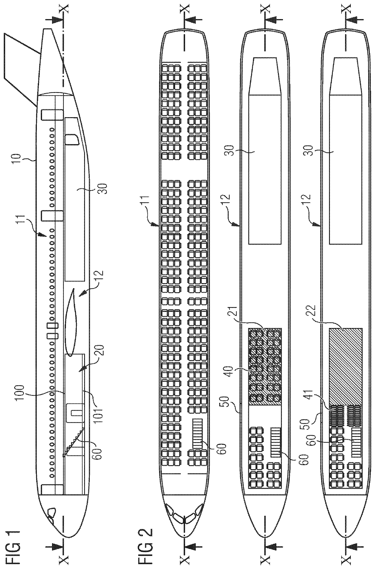
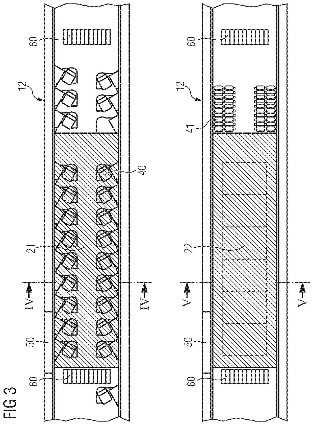
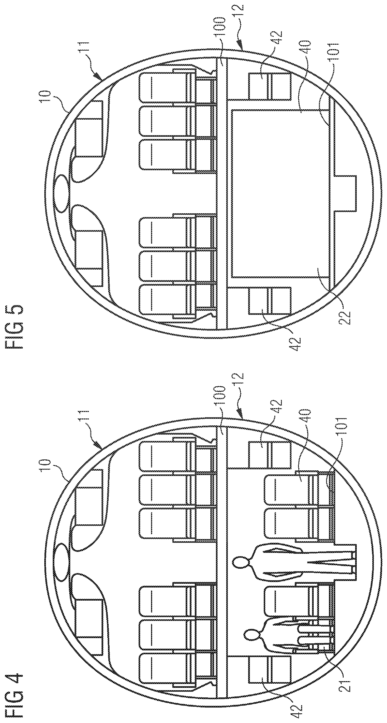
[0049]FIG. 1 shows, schematically, a vertical longitudinal section through an aircraft 10. An aircraft is illustrated here merely by way of example. The aircraft 10 has at least one deck 11, 12 (plane), in which passengers and / or cargo can be accommodated. The aircraft 10 which is shown in FIG. 1 thus has an intermediate floor 100, which separates an upper deck 11 from a lower deck 12. A flight of stairs 60 connects the upper deck 11 to the lower deck 12. The aircraft region 20 in the lower deck 12 also has a floor 101, and therefore an interior space of the aircraft is present between the intermediate floor 100 and the floor 101, for optional use as a passenger cabin or cargo space.

[0050]While a description is given hereinbelow, by way of example, of the ai...


PUM


Abstract

An aircraft-floor element comprising a first cladding element configure to be swung from a first position to a second position. In the first position, the first cladding element is arranged parallel to a main plane of the aircraft-floor element and on a side of the aircraft-floor element which is directed towards a passenger cabin. In the second position, the first cladding is arranged at an angle to the main plane of the aircraft-floor element, wherein it forms a cladding for a cargo space. An aircraft zone having an aircraft-floor element and an aircraft having such an aircraft zone are also disclosed.

Description

CROSS-REFERENCES TO RELATED APPLICATIONS[0001]This application claims the benefit of the German patent application No. 10 2018 117 024.6 filed on Jul. 13, 2018, the entire disclosures of which are incorporated herein by way of reference.FIELD OF THE INVENTION[0002]The invention relates to an aircraft-floor element having a swing-action cladding element, wherein, in a first position, the cladding element forms part of the aircraft-floor element and is directed towards a passenger cabin and, in a second, swung-out position, it forms a cladding for a cargo space.BACKGROUND OF THE INVENTION[0003]The attempt is made in many vehicles, in particular means of mass transport, for example, aircraft, trains, buses and ships, to make as versatile use as possible of the space available. For example, an interior space of an aircraft can be converted from a passenger cabin to a cargo space, and vice versa. For this purpose, the rows of seats in the passenger cabin have to be removed and, when the ...

Claims


Application Information

Patent Timeline
IPC IPC(8): B64C1/18B64D11/00
CPCB64D11/0023B64D2011/0046B64C1/18B64C1/066Y02T50/40
Inventor GROSS, CLAUS-PETER
Owner AIRBUS OPERATIONS GMBH
Learn More