
Redundant control system for an actuator and method for redundant control thereof

Active Publication Date: 2017-09-07
SIEMENS AG
View PDF0 Cites 0 Cited by
  • Summary
  • Abstract
  • Description
  • Claims
  • Application Information

AI Technical Summary

Benefits of technology

The invention aims to solve the problem of having a single control system fail in a critical infrastructure. The invention provides a redundant control system and method that allows for a quick switch between redundant output modules in case of failure.

Problems solved by technology

A problem for redundancy operation is produced by the determination of a particular reaction of the system when a device upstream of the output model, such as when the control computer or the field bus is interrupted or fails.
The established reaction mechanism therefore results in a complete redundancy failure.
Although this measure solves the problem, albeit with increased effort, it has the disadvantage that when their power supply is removed, the redundant output modules behave in an uncontrollable and undefined manner for a relatively long period, preventing a rapid changeover to the other redundant output module.

Method used


Image

  • Redundant control system for an actuator and method for redundant control thereof
  • Redundant control system for an actuator and method for redundant control thereof
  • Redundant control system for an actuator and method for redundant control thereof

Examples


Embodiment Construction

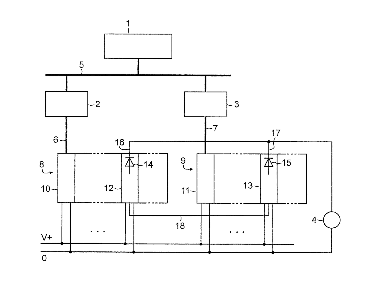
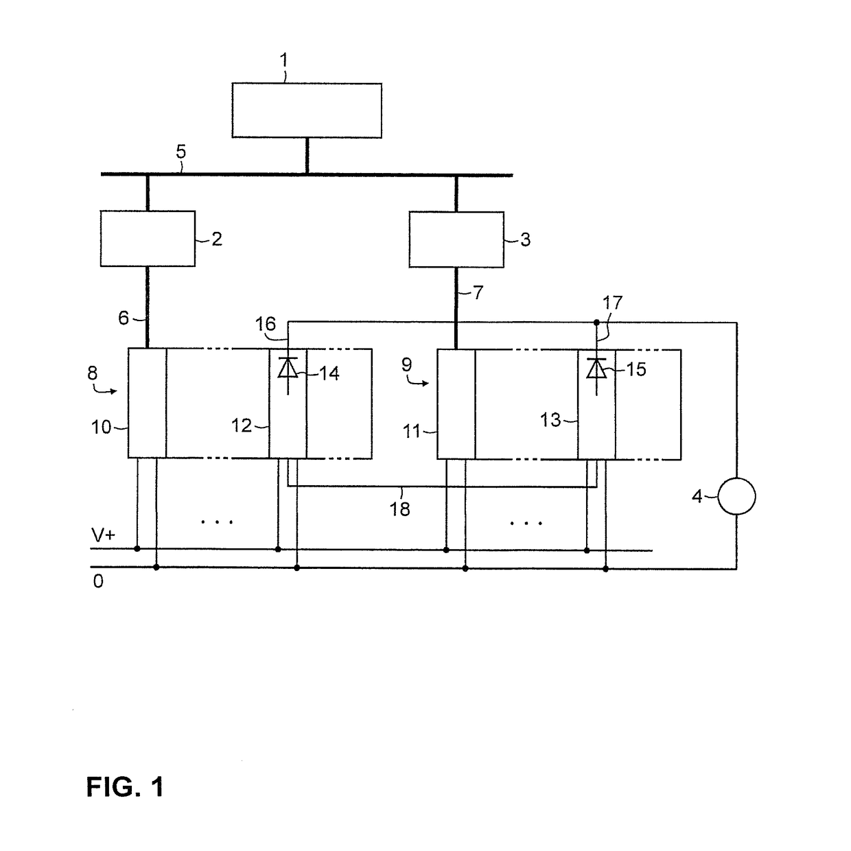
[0025]With reference to FIG. 1, shown is a section of a process control system with a controlling system 1 in a process management level, a first and second control computer 2, 3 in the form of memory-programmable controls in a control level and an actuator 4 at field level. The field level contains further field devices (not shown) which, in the form of sensors, record the states of a technical process and, formed as actuators, specifically influence the process. The controlling system 1 and the control computers 2, 3 are interconnected via a plant bus 5 (e.g., Ethernet). To generate output values for the actuator 4, the two control computers 2, 3 each execute one and the same control or user program in redundancy operation, inter alia, processing input data received from sensors over separate digital field buses 6, 7 (e.g., PROFIBUS DP). The field devices are connected to the field buses 6, 7 of the two control computers 2, 3 via a first and a second decentralized peripheral stati...


PUM


Abstract

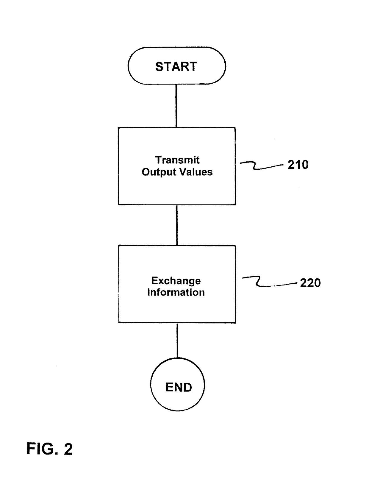
A method and redundant control system for an actuator in which two redundant control computers are connected via buses to a respective peripheral station containing an interface module and at least one periphery module, wherein the actuator is connected to mutually decoupled signal outputs of two periphery modules, each forming an output module, of the two peripheral stations, where output values generated by the two redundant control computers for the actuator are transmitted by the interface modules to the output modules, wherein upon detection of a bus fault, the respective interface module transmits a command to all downstream output modules to output substitute values, and where output modules to which the actuator is connected exchange information about receipt of the command via a communication link and implement it only if another output module concerned has also received the command so as to prevent failure modes in redundant operation.

Description

BACKGROUND OF THE INVENTION[0001]1. Field of the Invention[0002]The present invention relates to control systems and, more particularly, to a redundant control system.[0003]2. Description of the Related Art[0004]Process control systems, such as SIMATIC PCS 7 from Siemens, serve to automate processes in technical systems and are usually hierarchically structured by way of several layers. At field level, the states of the technical process are recorded (sensors) and / or the process specifically influenced (actuators) by field devices. At control level, control computers (stored program controls with CPU units) perform control and regulatory functions in proximity to the field, where they receive input values from the sensors, e.g., a pressure transducer, and deliver output values to the actuators, e.g., a positioner for a control valve. At process management level, superordinate control and regulation of the process occurs in host computers.[0005]Data exchange between field devices and...

Claims


Application Information

Patent Timeline
IPC IPC(8): G05B23/02
CPCG05B23/0286G05B9/03G05B19/052G05B19/058G05B2219/24173G05B2219/24182
Inventor MAIER, WILLIROTTMANN, NORBERT
Owner SIEMENS AG
Learn More